

![]()
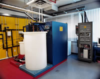 The FSEC Solar Thermal System Test Laboratory (STL) is used for performing tests of systems when the collector can not be easily isolated from the rest of the solar system and must be tested as a unit.
In the cases where the collector can be tested separately, those components are evaluated and measured in our solar thermal collector testing area.
The STL provides an area for heat loss and heat exchanger testing. These are the first series of tests on a system. The system is then moved to the rooftop area where it is tested for performance. The plumbing and instrumentation is routed to the STL below where there is a chilled and a heated water loop. The system is stabilized to a required temperature, exposed for a length of time, and then purged at the specified temperature to determine the heat gain.
Operation, monitoring, and data acquisition for the STL are under computer control. The purges are initiated electronically with solenoid valves.
Heating and Chilling
Two 240V, 9.5 kW instantaneous heaters with microprocessor-based PID temperature controllers are used to maintain stable water temperatures for testing. A 12,000 Btu water/water copper, heat exchanger which is plumbed directly into the chilled water loop of our facilities' central energy plant is used for water chilling. The chilled water temperature is adjusted with an electric valve actuator which is controlled by a microprocessor-based PID temperature controller.
Meteorological Station
The STL has a weather station on the roof directly above the lab. This station monitors the wind, ambient temperature, infrared, and solar incidence (horizontal, tilt and indirect). The data from this station is collected and processed by a computer.
Solar irradiance is measured with Eppley Laboratory Precision Spectral Pyranometers (PSP) mounted horizontally on a test stand in the rooftop testing area and on the collector stand in the plane of the collector.
The diffuse sky radiation is measured by an Eppley PSP used with an Eppley Shadow Band Stand which shields the sensing element of the pyranometer from direct solar radiation with an anodized aluminum band approximately 25 inches in diameter and 3 inches wide. The device is adjustable for latitude and solar declination. The Eppley PSP is rated as a first class instrument by the World Meteorological Organization. It meets all the requirements of ASHRAE 93-86 and 96-80 (solar collector testing standards).
Infrared radiation is measured with a pyrgeometer, the Eppley Precision Infrared Radiometer (PIR). A pyrgeometer measures the exchange of radiation between a horizontal blackened surface (the detector) and the target viewed (the sky). The (PIR) is designed to measure (unidirectional) incoming or outgoing long-wave terrestrial radiation. The instrument allows isolation of the radiation from the target impinging on the detector by automatically compensation for the detector flux.
Wind velocity across the system is measured using a three cup anemometer mounted in the rooftop testing area. The anemometer rotates a photo chopper which converts the rotation rate into electrical pulses. The frequency of the output signal is proportional to the wind speed. The variable frequency signal is converted to a DC voltage by the signal conditioning equipment in the systems laboratory and digitized by the Data Acquisition System. Specifications on the wind velocity instrument exceeds the requirements of ASHRAE 93-86.
Ambient air temperature is measured using a platinum resistance thermometer (RTD) mounted in a shield which is constantly aspirated with an electronic fan. The shield prevents direct solar heating of the RTD while allowing the flow of ambient across the sensor.
Data acquisition and laboratory control
All instrumentation for the laboratory is controlled by a Pentium processor based system using a National Instruments SCXI chassis, modules and DAQ boards. The process is automated using National Instruments "LAbView" graphical programming language. Temperatures are measured using platinum resistance temperature thermometers and type T thermocouples. Flow measurements are taken with turbine flow meters mounted in the fluid line. Flow is also calculated using two 2,000 lb. scales with digital weight indicators having an accuracy of 1:10,000. Flow is controlled using two positive displacement gear pumps with 1 H.P. motors and digital motor speed controllers.
Safety
The computer monitors the laboratory for several alert conditions. Devices are in place to detect overheating, flooding and over-pressurization. The system is designed to safely shut down if any of these conditions are detected protecting both the laboratory and any equipment currently under test.
Exposure and Pressure Testing
Systems are subjected to outdoor exposure in a fenced security area on site. Pressure testing and system check-in and inspection is performed in our high-bay area.
Calibration
All of the instruments in the laboratory are calibrated on a routine basis as recommended by the equipment manufacturer to maintain accuracy or as required by ASHRAE 93-86 or 96-80. In case of a conflict between the two recommendations the shorter time period will be used. In no case will the period between calibrations exceed one year.
Procedures
For detailed information on the procedures followed in our system and collector testing program please see FSEC's Testing & Certification site.
© 2007-2014 University of Central Florida. The Florida Solar Energy Center (FSEC)
is a research institute of the
University of Central Florida.
For more information about FSEC, please contact us or learn more about us.
Find us on Facebook!