

Reference Publication: Peer reviewed symposium paper presented at: Twelfth Symposium on Improving Building Systems in Hot and Humid Climates May 2000 San Antonio, Texas Disclaimer: The views and opinions expressed in this article are solely those of the authors and are not intended to represent the views and opinions of the Florida Solar Energy Center. |
Building
Envelope Air Leakage Failure in Small Commercial
Buildings
Related to
the Use of Suspended Tile Ceilings
Charles
R. Withers Jr. and James
B. Cummings
Florida
Solar Energy Center (FSEC)
FSEC-PF-398-00
1. Abstract
Recent research over the last few years is providing a better understanding about the building envelope of small commercial buildings. These buildings have very similar construction to single-family residential buildings, but unlike residential buildings, they usually have a suspended tile ceiling between the conditioned space and ceiling or attic space. Testing indicates that the building envelope in small commercial buildings is substantially less airtight than residential buildings and the cause is associated with the suspended ceiling. Ceiling airtightness test results from two buildings are presented in this paper and show that they are very leaky. The pathways in the ceiling plane are one necessary constituent for airflow to occur across the ceiling. The second constituent needed is a pressure difference across the ceiling. Data and observations from three buildings are used to illustrate the impact that four primary driving forces and a leaky ceiling have on small commercial buildings. The severity of impact from ceiling air leakage failure depends on the amount, direction, and quality of airflow.
2. Introduction
Building envelope air tightness in commercial buildings has received considerable research attention in recent years. Persilly (1999) presents an overview of airtightness tests in 139 commercial buildings, the largest majority of which have been studied in the past 10 years. The resulting knowledge about the airtightness of building envelopes provides the basis for improved design of buildings or diagnosis of building problems. Knowing building tightness can help one predict pressures or net airflow across the building air barrier, and this information can be used to understand more about the indoor environment. Natural ventilation rates can be estimated and mechanical induced ventilation rates can be calculated with an understanding of building pressure with reference to outside, duct leak amounts and location. Building tightness measurement helps us gain a better understanding about a building, but does not break the leakage down by location since it is very difficult to quantify the airtightness of individual components of the envelope such as the ceiling or wall tightness. Therefore, very little can be said about the quantity of air that may travel through one particular plane such as the ceiling and the impacts of uncontrolled air flow upon the conditioned space. This paper focuses on building failures associated with the suspended ceiling plane in small commercial buildings.
Research of 69 small commercial buildings in Florida has shown that they are much leakier than new residential buildings. The average airtightness, normalized by volume, of 69 small commercial buildings was 16.7 air changes per hour when the building was at 50 pascals (Pa) of pressure (ACH50) (Cummings et al, 1996). New single-family residences average about 6 ACH50 and houses ten or more years older average about 12.6 ACH50 (Cummings et al, 1991). One very clear distinction between small commercial and residential buildings is the use of suspended t-bar ceilings in commercial ceilings. When the sample of 69 buildings is carefully screened for those most similar to single family residential construction, nine buildings are identified with single story, slab on grade, concrete block or wood frame exterior walls, and ventilated attic or ceiling spaces. All 9 buildings have suspended ceilings. The average floor area is 2976 square feet, average ceiling height is 9 feet, and average ACH50 is 22.9. If average residential airtightness is about 10 ACH50, then small commercial buildings of similar construction are about 2.3 times leakier. Since the only significant difference between these samples of residential and small commercial buildings is the ceiling, this strongly suggests that suspended ceilings are very leaky and constitute the majority of envelope leakage in small commercial buildings.
CEILING TIGHTNESS MEASUREMENT
Although research shows small commercial buildings are leakier than residential buildings and the suspended ceiling is likely the reason, little is known about the airtightness of installed ceiling tile systems. There are several styles of tile composed of different materials ranging from the standard gypsum or cellulose product to foil backed or insulated tiles. Some of these are very dense and rigid while others are lightweight and flexible. It is likely that the airtightness of a ceiling will change depending on what type of ceiling tile is used.
Some precautions should be taken when depressurizing buildings with suspended ceilings. A ceiling system that was not installed correctly could be pulled down in weak places when depressurizing at higher pressures. Tiles may also be sucked into the space if they are flimsy or installed into a frame that is not correctly sized. The authors have had ceiling tiles fall out on several occasions.
If the test is completed by pressurizing, there is the likelihood that loose fitting tiles may be pushed open at higher test pressures. This indicates that the airtightness may change depending on the pressure differential that occurs across the ceiling. A typical 4 square foot ceiling tile weighs only 4.2 pounds. A pressure greater than 35.7 Pa across the tile is enough to begin to push the tile upward thereby increasing the hole in the ceiling plane. The preceding statement is true in the absence of frictional forces which act between the metal frame and sides of the tile. There is typically some friction, but loose tiles are likely to occur somewhere in the ceiling. The authors have observed tiles float significantly when the conditioned space was about 45 Pa with reference to (wrt) the ceiling space. This produced a noticeable change in the flow curve when a multi-point test was conducted. It should be noted that in this case the airtightness of a room with a suspended ceiling was being tested for training purposes. As a general practice it is recommended that airtightness be measured by depressurization. If there are air quality concerns regarding contaminants such as dust, odors or toxic fumes being drawn into the conditioned space, the building could be pressurized using a multiple point sample up to a pressure of about 35 Pa.
While testing a large community center, one room was selected to measure ceiling airtightness. This room had tight walls and floor with a suspended tile ceiling. Three walls were painted concrete block and one was a painted gypsum board wall. The floor was tile over concrete slab. The ceiling space above had a large area of vents to outdoors. This means that the ceiling space ventilation holes are much larger than the leaks in the ceiling plane and they will not restrict airflow through the ceiling.
Consider a different example, for a moment, where the ceiling space vent openings have much less leak area compared to the ceiling, and the walls and floor are tight, but the ceiling plane is very leaky. The airflow through a blower door fan will be much smaller because the controlling aperture is now at the ceiling space vent to outdoors. Although significant ceiling leak pathways exist, the wall and floor are tight so the only way for air to pass through the ceiling during testing is if the ceiling space is vented. The ceiling space vent area compared to the ceiling leakage area influences how much air flows across the ceiling. The ceiling and the ceiling space vents can be thought of as series resisters (Blasnik and Fitzgerald, 1992). Since the leak area of the ceiling space vents is much greater than the leak area of the ceiling of our test room, the resistance to air flow of the ceiling space vents is negligible.
The test room floor area was 352 square feet with one set of double doors into it. Lighting was provided by 2' x 4' drop-in fluorescent light fixtures. Blower door test equipment was placed in one doorway and air pathways through the door undercut were sealed with tape. The two 2 foot by 2 foot air distribution registers (representing 2.3% of ceiling area) were sealed off during the test to eliminate duct pathways and leaks from being measured. While the room was depressurized, the wall electric outlets were checked to see if air leakage occurred through them and it was verified that a negligible amount existed. Visual observations determined that the wall and floor construction was very airtight. Therefore, it was concluded room construction other than the ceiling is very tight and that the measured airtightness of the room should be essentially the airtightness of the ceiling. The ceiling was typical suspended t-bar frame with 2' x 4' acoustical cellulose material tile 9 feet above the floor, and there were no cracked or missing sections of tile.
Figure 1 shows a plot of the air flow versus airtightness of the ceiling. The amount of leakage is measured as airflow in cubic feet per minute when the building is depressurized to 50 Pa also known as CFM50. The CFM50 of the room was 1776. The variables n and C are shown in figure 1 and can be used to calculate airflow for the building if the pressure is known using the equation Q = C x dP n where Q is airflow, C is the flow coefficient, n is the flow exponent, and dP is the differential pressure. The normalized airtightness (mentioned previously as ACH50) is 33.6. ACH50 was calculated as follows: 1776 ÷ 3168 ft3 room volume x 60 = 33.6 ACH50. When the ceiling tightness is normalized by the square foot area of the ceiling, CFM50 per square foot of ceiling area is 5.0.
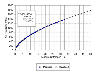
Figure 1. Ceiling Airtightness Flow Curve
Measurements at another building also found ceiling tightness of a typical suspended ceiling to be about 5.0 CFM50 / square foot of ceiling area. This test was conducted in an office space located within an unconditioned warehouse. It had R-19 batts located on top of a suspended ceiling. The 360 square foot ceiling area had 64 square feet of 2 foot by 4 foot drop-in fluorescent lighting fixtures (17.8% of total area) and 20 square feet of 2 foot by 2 foot air diffusers (5.5% of total area). The diffusers were sealed off during testing. The office space was tested once to obtain total CFM50 for the building (registers sealed) and then was tested a second time with the warehouse at the same -50 Pa pressure as the office space. By this method, we were able to subtract the “leakiness” (CFM50) of three of the four walls of the office space. For the fourth wall (common between office and warehouse), we calculated the CFM50 that would likely occur because of cracks and undercuts around the doors and assumed that the leakage of the remainder of the wall was very small. Based on this, ceiling leakage is calculated to be 1788 CFM50 (CFM50ceiling = 2103 - 314.8 = 1788). This equates to 5.0 CFM50/sqft.
Additional research will be required before a range of tightness and average tightness can be determined, however preliminary tests show that small commercial suspended ceilings have approximately 5 CFM50/square foot or are about 10 times leakier than the typical residential gypsum board ceiling. This leakiness creates a large potential for airflow across the ceiling plane, and if the ceiling space is vented it is likely that the building will be very leaky. In the southeastern part of the United States a vented attic or ceiling space will also be hot and humid much of the year and this can have tremendous impacts on the building and air environment as will be shown later.
DRIVING FORCES
The fact that there are significant pathways across the ceiling do not guarantee significant amounts of airflow will be transferred across it. In addition to a pathway, there must be a driving force (pressure differential) across the pathway for airflow to occur. There are four primary driving forces that were determined to cause uncontrolled airflow in small commercial buildings. 1) natural 2) duct leakage 3) restricted return air, and 4) unbalanced exhaust (Cummings et al, 1996). A brief explanation of each of these will help provide a better understanding of why some buildings experience problems while others do not.
Natural driving forces such as wind or temperature differences between conditioned and unconditioned spaces can cause air to move through holes in the envelope. Wind causes positive pressure on the windward side of a structure which results in outside air being driven into the building wherever pathways exist. Wind on the leeward side or even walls or roof parallel with the direction of wind can result in negative pressures on the building’s exterior surfaces which can cause air to be pulled from indoors to outdoors through pathways.
The following illustrates an envelope failure associated with a suspended ceiling and wind. An observation was made by the lead author while characterizing uncontrolled airflow at a business in a strip mall. The retail business, located in east central Florida, faced south and could only be entered from the south side through double doors The roof was flat and was well ventilated. Most of the 2 foot by 4 foot ceiling tiles were the cellulose type, however, several had been replaced with much lighter vinyl faced fiberglass tiles. Wind was about 15-20 miles per hour out of the southwest on the day of observation. As customers would come into the store the door would slowly close as the closure arm fought to pull the door against the force of the wind. While the door was open, one of the light ceiling tiles would swing open with one side staying in the t-bar frame as the tile hinged upward into the ceiling space. This occurred many times throughout the day.
Air at different temperatures will have different densities. Warm, less dense and therefore more buoyant air, will rise up through cooler air. This natural air driving force, stack effect, has greater impacts in cold climates where temperature differences between indoors and outdoors are greater than in warmer climates. In cold climates, the relatively warm indoor air tends to rise and leave the building through high leak pathways. In warm climates, the relatively cool indoor air tends to sink and leave the building through low pathways.
Duct leakage transfers unconditioned air into the building through return leaks that are located outside the conditioned space or it may transfer conditioned air out of the building when supply leaks are located in an unconditioned location. When there is more supply leakage than return leakage, more air is transferred out of the building than is brought in through return leaks, causing the building to become depressurized. This depressurization draws air into the building through the path of least resistance, and this pathway is often the suspended ceiling. In hot and humid climates, the energy, humidity, and comfort impacts of air entering from a hot and humid ceiling space can be substantial. In cold climates, return dominate leakage has serious implications as warmer dewpoint air may be pushed into cold building cavities.
Restricted return air occurs when supply air is distributed to rooms that can be closed and have undersized return air or no return air. This is very common in Florida residences and small commercial buildings. This problem results in depressurization of the zone where the return is located and pressurization of the zone where the supply is transferring air behind a closed door. Unconditioned ceiling space air will be pulled into the depressurized zone and conditioned air will be pushed from the pressurized room into the ceiling space.
Unbalanced exhaust air results from exhaust fans pulling more air out of the building than make-up air and outdoor air drawing into the building. This creates a depressurized building that pulls unconditioned air from the ceiling space into the conditioned space.
PRIMARY AIR AND THERMAL BARRIERS
The term primary barrier is used to identify a location where most of the air or thermal resistance is located, however it does not imply that a substantial resistance exists. The primary air barrier is determined by a relative relationship between the ceiling plane and the outer envelope of the attic (roof deck). With the building depressurized to 50 Pa by the calibrated fan, pressures in various zones of the building are measured in order to know which portions of the building are within the building air barrier and which are not. The following example illustrates the principle. If the ceiling space is -10 Pa (wrt outdoors) when the occupied space is -50 Pa, this shows that the ceiling space is very well ventilated to outdoors, and that the suspended ceiling, though it may be very leaky, is the primary air barrier. Being the primary air barrier simply means that it is more airtight than the ceiling space is to outdoors.
Previous work has identified eight different ceiling space configurations found in small commercial buildings (Cummings et al, 1996). The configurations show whether the space is ventilated and if the primary air barrier is at the ceiling plane or roof deck. It also shows where the primary thermal barrier (insulation) is located. For instance, a non-vented ceiling space with the thermal barrier at the roof deck (type 2) would be cool and dry in the summer. Comfort, energy and humidity impacts from airflows across the ceiling plane in this type of building will be small. However, if the ceiling space is vented and the thermal barrier is located on the ceiling, the comfort, energy, humidity, and ventilation potential impacts will be large.
AIR LEAKAGE FAILURES RELATED TO SUSPENDED CEILINGS
Three case studies using buildings located in central Florida are presented in this section to illustrate the role that suspended ceilings can have when different driving forces act across them.
Realty Office With Duct Leaks and Unbalanced Exhaust
Testing in a realty office was conducted in response to occupant comfort
complaints. This single-story building was built in 1971 and has
a floor area of 1845 square feet. The walls consist of concrete block
with stucco exterior on the east, west and north sides of the building,
and brick exterior on the south wall. A t-bar tile ceiling is suspended
about 8 inches below a wood truss system. Faced R-19 batt ceiling
insulation was attached to the bottom side of the wood trusses. The
attic space was continuously ventilated by a 700 cfm exhaust fan
and had two vents each with net free area of 0.83 square feet located
in the south eave.
Air was distributed from the air handler through duct board ducts located in the attic above the primary thermal barrier (ceiling insulation). The air handler was located on top of an enclosed support platform in a storage closet within the conditioned space. The enclosed support platform was used as a return plenum with a single transfer grill through a wall of the platform to the central area of the building. There was no return leakage from outside the conditioned space because the wall cavity at the return grill had been sealed using mastic. While there was no significant return leakage, there was severe supply duct leakage in the attic that resulted from metal tape failure.
Initial testing found that the building was severely depressurized and very humid. When the building was depressurized to 50 Pa with a blower door, the attic space was depressurized to 43 Pa. This shows that the primary air barrier was the roof deck and that the suspended t-bar ceiling provides much less resistance to air flow than the ventilated attic. The attic exhaust fan caused negative pressure in the attic space of about -15 Pa, and this depressurization was causing air to be drawn through the suspended ceiling into the attic. When the air conditioner was operating, large supply leaks were also causing uncontrolled air flow by dumping supply air into the attic and depressurizing the occupied space. While building conditions were monitored, duct leaks were repaired then the attic exhaust fan was turned off. Table 1 summarizes some of the surprising monitoring results.
Table 1: Impact of Repair of Uncontrolled
Airflow upon Ventilation Rates, Indoor Relative
Humidity, and Building Pressure with Respect to Outdoors when Air Handler
is On.
(Relative humidity, and building pressure are shown as the daily average.)
(Withers and Cummings, 1998)
Type of Repair |
Air Changes per Hour AH on |
Relative Humidity % |
Building Pressure (Pascal) |
Attic Pressure (Pascal) |
Pre-repair |
0.87 |
72 |
-14.3 |
-13.7 |
Duct repair |
0.79 |
77 |
-15.9 |
-16.4 |
Attic fan off |
0.33 |
61 |
-0.6 |
-0.6 |
After duct repairs were complete, the building ventilation rate declined slightly from 0.87 air changes per hour (ach) to 0.79 ach and CFM25 in the ducts decreased by 80% from 571 to 112. Notice in Table 1 the indoor relative humidity increased because air conditioner run time decreased by about 30% while the building ventilation rate remained largely unchanged. Building depressurization did not disappear until the attic exhaust fan was turned off. Turning off the attic exhaust fan also caused daily relative humidity levels to decrease from 77% to 61% and from 68% to 55% during normal business hours of 11 AM to 5 PM (Figure 2). It also caused the building ventilation rate to decreased from 0.79 ach to 0.33 ach.
Figure 2. Relative Humidity in Office
As a result of duct repair, average cooling energy consumption (based on a TMY predicted eight-month cooling season) decreased from 99.6 kWh/day to 69.1 kWh/day (31% savings) and cooling peak demand decreased by 20% from 6.5 kW to 5.2 kW. As a result of turning off the attic exhaust fan, average cooling energy consumption (based on an eight-month cooling season) decreased by an additional 14.3 kWh/day (36%) and peak electric demand (including attic fan power of 0.47 kW) was reduced by 21% from 3.4 kW to 2.7 kW.
The leaky suspended ceiling played an important role in the behavior of this building. If the ceiling had been a relatively airtight gypsum board ceiling, things would have been different. The depressurization caused by the attic exhaust fan would have largely remained in the attic space thereby diminishing the impact on the conditioned space. On the other hand, the large supply leaks in the attic would have caused substantial depressurization of the occupied space. Duct repairs alone would have reduced the cooling energy waste, high indoor relative humidity, and the elevated ventilation rates.
Restaurant With Unbalanced Exhaust
This five year old chain steak restaurant was tested following moisture
and comfort related complaints. All of the dining area ceiling tiles
had been replaced just prior to testing due to sagging caused by
high humidity. This cost the restaurant about $11,000. The building
was 6115 square feet with 6 inch metal stud walls insulated with
6 inch thick fiberglass batts, ½ inch
plywood with painted lap wood siding, and insulation integrated into
a flat roof system. The building is cooled by 5 roof top air conditioning
units (RTU) each with outside air. The air ducts consist of fiber
glass ductboard main and insulated flexible duct register branches
which are located in the ceiling space. Five exhaust fans and 2 kitchen
exhaust make-up air fans serve the building. The make-up air was
linked to the exhaust fan switch so that it operated at the same
time as the three kitchen exhaust fans.
Preliminary testing and inspection found the building to have an airtightness of 12,021 CFM50. This calculates to an ACH50 of 14.1 based on an occupied conditioned space of 6061 square feet with ceiling at 8.5 feet. This building was tighter than the average of 69 small commercial buildings mentioned previously. The primary air and thermal barriers were identified to be at the roof deck. When the building was depressurized to 50 Pa with reference to outside, the ceiling space was -42.9 Pa with reference to outside. The pressure drop across the ceiling was only 7.1 pa. The building normal operating pressure, which is the indoor pressure with reference to outside when all RTU’s are on, kitchen exhaust, and make up air fans are operating, was -2.7 Pa. The dishwasher exhaust only operates part time so it was not turned on, however the building pressure becomes -5.0 Pa when it is turned on. The negative building pressure indicates that the total exhausted air from the building exceeds the total incoming air. Short-term monitoring of space conditions revealed interesting findings for this building about unbalanced exhaust flow and leaky ceilings as is shown in Figure 3.
 |
Figure 3. Restaurant Dewpoint
Temperature and Pressure With Reference to Outside With Kitchen
Fans On and Off |
Monitoring for several days showed the same pattern repeated daily. Workers would turn on the kitchen exhaust between 9:00 and 9:30 am and turn them off about 1:00 am. The ceiling space and conditioned space dewpoint go up drastically when the kitchen exhaust fans were turned on and would drop after the exhaust was turned off. When the exhaust fans are turned on, the ceiling space dewpoint increases to values near the outdoor dewpoint indicating this space becomes filled with outside air. The building operated at about -2.7 Pa due to the unbalanced exhaust air of the building. This caused the ceiling space to also be depressurized about the same amount. Although the primary air barrier is at the roof deck and walls of the ceiling space, this does not mean it will act as a good air barrier. In fact, all around the perimeter walls of the ceiling space there are significant pathways between the ceiling space and the exterior vented soffit space. Notice also in the figure that the building pressure becomes positive once the exhaust fans are off and the ceiling space dewpoint becomes drier as conditioned air is pushed up through the ceiling into the space. This is due to more air being brought into the restaurant from the outside air than what is being exhausted.
A retrofit plan was developed that included recommendations to reduce kitchen exhaust flows to a minimum amount that would still effectively capture all cooking effluent. Capture would also be improved by increasing make-up air flows to 80 % of the exhaust flow and modifying delivery of make-up air so that it is discharged outside the hoods. The outdoor air should be enough to satisfy ventilation requirements and at least 21 % of the exhaust flow. The last recommendation was to air tighten the ceiling space. With these changes, the building would be more airtight, operate under a significant positive pressure, and the ceiling space would then maintain lower relative humidity thereby preventing further damage to the ceiling tiles.
The recommendations were made to the restaurant which took responsibility
of implementing the changes. Recommendations have been partially implemented
at this time. The ceiling space has been tightened resulting in a total
building tightness of 8867 CFM50 (10.2 ACH50). This is a 26 % improvement
in building tightness, however, a target tightness of about 8 ACH50
was suggested. Modifying fan flow rates, the other portion of the recommendations,
was recently carried out by a national test and balancing firm, but
follow-up monitoring has not occurred and indoor temperature and relative
humidity conditions are not know at this time.
Metal Office Building With Restricted Return
This metal office building had a floor area of 3672 square feet with
metal structure support beams, metal exterior siding, and sloped metal
roofing. The primary thermal barrier, R-19 insulation batts, were on
top of the suspended ceiling. A second thermal barrier, 1 inch thick
vinyl-faced insulation, was placed against the metal roof deck inside
the ceiling space. The roof deck insulation was run down into the walls
also. The ceiling space was not ventilated. Testing established that
the building was tighter than the average commercial building, with
3545 CFM50 and ACH50 of 7.0. When the building was depressurized to
50 Pa wrt outdoors using a blower door fan, the ceiling space pressure
was at -47.5 Pa wrt outdoors. This indicates the roof deck is the primary
air barrier.
The building was air conditioned using two air distribution systems with all supply ductwork located in the ceiling space. The west system air handler was located in the ceiling space with a return ducted to a main hallway, however, the east system air handler was located on top of an unfinished support platform in a mechanical closet that was used as a return. A transfer grill from the room to the main hallway served as the pathway from the building back to the air handler. Use of the mechanical room as a return plenum caused it to be depressurized to -19.1 Pa wrt the ceiling space when the air conditioner operated. Since the depressurized mechanical room has a suspended ceiling, 28% of the return air was coming from this relatively hot (though dry) ceiling space (Figure 4). As a general rule, building cavities such as mechanical rooms, walls cavities, closets, storage rooms, panned floor joists, etc. should not be used as a portion of the air distribution system since they are not built to the same airtightness standard as ductwork.
 |
Figure 4. Airflow Failure
Through Suspended Ceiling in Room Used as a Return Plenum |
The business did not want to “hard duct” the return from the hallway to the east system return because they would lose valuable storage space. Since the room had to be used as a duct, efforts were made to make it more airtight to the ceiling space. The seams in the suspended ceiling were sealed with clear caulk and several tiles were adjusted so they fit in the t-bar grid more tightly. More importantly, the room was made leakier to the hallway by installing a louvered door to replace a solid door. As a result, the mechanical room pressure decreased, from -19.1 Pa to -4.2 Pa and return leakage decreased from 28% to 4%.
Reducing the air flow across the mechanical room ceiling by 86% decreased the cooling energy by 10.8% from 87.2 kWh/day to 77.8 kWh/day. Repair time was 5 person-hours and $90 in materials. The payback is projected to be 2.2 years based on monitored energy savings and $340 repair cost. If the ceiling space had been vented, the energy penalties associated with this uncontrolled air flow across the mechanical room ceiling would have been much greater.
CONCLUSIONS
Suspended ceilings in the typical small commercial building do not offer much resistance to airflow because of the seams on four sides of each tile and the numerous amount of tiles used. Preliminary testing indicates that the typical ceiling airtightness may be about 5 CFM50 for every square foot of ceiling space. Air movement will occur across suspended ceilings when a pressure differential exists across it. Four driving forces that cause pressure differences are identified: 1) wind and temperature, 2) duct leakage, 3) restricted return air, and 4) unbalanced exhaust air. In many small commercial buildings, mechanical driving forces dominate.
Air flow from the ceiling space into the conditioned space is undesirable for many reasons and building designers and contractors should take into account the leakiness characteristics of suspended ceilings. Either the suspended ceiling should not be considered to be the primary air boundary or a different ceiling construction should be used.
The severity from air flow across the ceiling plane depends upon three basic things. They are the amount, direction, and the quality of the air flow from the ceiling into the conditioned space. The amount of airflow will depend on how leaky the ceiling and ceiling space is and how large the driving forces are. The direction of air flow is determined by whether the conditioned space is at a positive or negative pressure with reference to the ceiling space. The quality of the air flow from the ceiling space depends on how close the temperature and relative humidity are to comfortable conditions and if there are pollutants such as allergens in the air. If the insulation is located at the roof deck, the ceiling space is not vented, and the building operates at positive pressure, then the ceiling space will remain cool and dry (summer), and the consequences of uncontrolled air flow will be greatly diminished. If, on the other hand, the ceiling space is hot and humid (summer) and the building is depressurized, then problems such as moisture damage, elevated indoor humidity, diminished comfort, and increased cooling energy costs can occur. With building testing, inspection and careful consideration of the building operations and use, building failures can be turned into building victories.
ACKNOWLEDGMENTS
The authors would like to thank Ed Cobham and staff of the Florida Energy Office for funding that has made this paper possible and that has helped develop a better understanding of uncontrolled air flows in buildings.
REFERENCES
Blasnik, M., and J. Fitzgerald. 1992. “In Search of the Missing Leak” Home Energy, Nov / Dec, p.27-32.
Cummings, J.B., J. Tooley, N. Moyer. 1991. “Investigation of Air Distribution system Leakage and Its Impact in Central Florida Homes; Final Report” FSEC-CR-397-91 Florida Solar Energy Center, Cape Canaveral, FL, January, 1991.
Cummings, J.B., C.R. Withers, N. Moyer, P. Fairey, and B. McKendry. 1996. “Uncontrolled Air Flow in Non–Residential Buildings; Final Report” FSEC-CR-878-96 Florida Solar Energy Center, Cocoa, FL, April, 1996.
Persily, Andrew K., "Myths About Building Envelopes", ASHRAE Journal, Mar, 1999, p.39 -47.
Withers, C.R., J.B. Cummings. 1998. “Ventilation, Humidity, and Energy Impacts of Uncontrolled Air Flow in a Light Commercial Building” ASHRAE Transactions, Vol.104, Part 2, p. 733-742.
© 2007-2014 University of Central Florida. The Florida Solar Energy Center (FSEC)
is a research institute of the
University of Central Florida.
For more information about FSEC, please contact us or learn more about us.
Find us on Facebook!