

Reference Publication: Cummings, J.B., "Tracer Gas as a Practical Field Diagnostic Tool for Assessing Duct System Leaks", Proceedings of 6th Annual Symposium on Improving Building Systems in Hot and Humid Climates, Dallas TX, October 1989. (FSEC-PF-195-90) Disclaimer: The views and opinions expressed in this article are solely those of the authors and are not intended to represent the views and opinions of the Florida Solar Energy Center. |
Tracer
Gas as a Practical Field Diagnostic
Tool for Assessing Duct System Leaks
James
B. Cummings
Florida
Solar Energy Center (FSEC)
FSEC-PF-195-90
Abstract
A methodology is presented for using tracer gas testing to detect
and quantify duct leakage in homes. Since air is invisible, leakage
of air from duct systems often remains undetected. Smoke sticks used
in conjunction with blower doors are excellent diagnostic tools for
detecting and locating leaks in the air distribution system. The tracer
gas tests described are a good complement to these tools in the detection,
location, and measurement of duct leakage.
Testing for house infiltration once with the air handler on and again with the air handler off indicates whether duct leaks exist. In many cases, it is possible to determine the leak flow rate. A second part of the test, determining the return leak fraction by comparing the tracer gas concentration at the return and at a supply, can provide more accurate determination of the leak flow rate and whether it is a supply or return leak.
The tracer gas test methodology enables fairly accurate assessment of the energy impacts of the leaks and whether repair will be cost—effective. Finally, the tracer gas test can be repeated after repairs have been completed to ensure that the duct leaks have been sealed.
Problem Statement
Leakage in residential forced air systems occurs when ducts, plenums, and air handlers are not completely sealed. These leaks often go unnoticed. Unlike leaks in plumbing systems, which are usually very obvious, duct leaks are easily ignored because leaking air is invisible and leaves no destructive evidence. Severe leakage can cause observable degradation of space conditioning capacity and efficiency but this can often be mistakenly attributed to other causes. One usually has to use special techniques to detect and locate duct leaks.
Duct leaks can occur either to and from the conditioned space, or to and from unconditioned space. Only the latter causes major impacts upon comfort and space conditioning energy use. Therefore, when we measure duct leaks, we are not as much concerned about the total leakiness of the ducts as we are duct leaks into and from unconditioned spaces.
Leaks in the supply ductwork are the most easily detected. When the air conditioner or furnace is operating, cooled or warmed air can be felt by the hand if access to the ductwork is available. This technique is commonly used when energy auditors check air distribution systems. Since ductwork is commonly located in attics or crawlspaces, which are often very restricted and not pleasant places in which to move around, thorough checking is often not done.
Leaks in the return ductwork are more difficult to detect. Air drawn into the suction side of the air distribution system cannot normally be detected by the human hand. Supply air has been either cooled or heated, so the temperature difference can be sensed. Return air is not different in temperature from the surrounding air. The supply leak comes out of an opening in a jet, which can be felt. Return leaks do not produce detectable high velocity air. Return leaks often remain undetected because (as the author has observed) people assume that return leaks are relatively unimportant compared to supply leaks.
Available Leak Detection Techniques
Therefore, diagnostic tools for detecting duct leaks are needed. Smoke sticks are a valuable tool. With the air handler running, a puff of smoke can be useful in identifying both supply and return leaks, because the invisible movement of air can now be seen. Use of a smoke stick can produce a much more complete assessment of the location and approximate size of duct leakage. No diagnostician should be without one.
Blower doors are very effective diagnostic tools in finding duct leaks, especially in conjunction with a smoke stick. By pressurizing the house to a moderate pressure, say 10 or 20 Pascals (Pa), a smoke stick can be used to observe how rapidly air is leaving the house through each supply and return register. (This, of course, is done with the air handler off.) If there are no leaks the smoke will not enter the register. If there are small leaks in the duct system, the smoke will go through the registers “lazily”. However, when the duct leak is large, the smoke will pass into the register rapidry. The closer the register is to a large leak, the faster the smoke will pass into the register.
The blower door can also be used to quantify the leak area of the air distribution system. The effective leak area (ELA) of the duct system can be determined by testing the house once with the supply and return registers open and then a second time with them sealed. The difference in the ELA of the two tests indicates the duct ELA. This can be used to estimate the flow rate of air leakage to and from unconditioned space. The accuracy of this estimate is dependent upon a good estimate of the pressure diffential across the leaks. In a given system, it is possible to measure pressure differences, but since they vary considerably across the system, the predicted air leakage may be greatly in error.
Tracer Gas Diagnostics
Tracer gas testing can be used as a diagnostic tool for identifying and quantifying duct leaks. There are two parts to one test w)iich can identify the quantity of leaking air. One part is to measure the infiltration rate of the house once with the air handler running and then again with the system shut off. A higher infiltration rate with the air handler “on” indicates duct leakage and can be used to make a reasonable estimate of the quantity of duct leakage. The second part is to observe the tracer gas concentration in the m at the return(s) and at a supply when the air handler is running. If there is no decrease in concentration from return to supply, then there is no leakage in the return side of the air distribution system (from outside the conditioned space). If there is a decrease in concentration from return to supply, then a return leak exists and can be quantified. The following is a description of the equipment, test procedures, and calculations used in these tests.
Test Equipment
The primary piece of equipment is a specific vapor analyzer designed to detect sulfur hexafluoride (SF6) concentration. It offers two ranges, 0 to 5 parts per million (ppm) and 0 to 50 ppm. It is an 18 pound portable instrument which has a 1.06 cfm (0.5 L/sec) air pump for sampling room air. It operates on the principle of infrared detection. Using a high temperature emitter and a detector, it determines the concentration of SF by the amount of infrared absorption at tfIe 10.7 micron wave length. Because its operating principle is thermal detection, changes in its internal temperature cause drift in its zero. Therefore, it is important to let the instrument warm up to a stable operating temperature, and to maintain fairly constant room conditions during the experiment. In order to reduce the sensitivity of the instrument to changes in room temperature, the outside case of the instrument has been insulated. In order to maintain maximum accuracy, it is recommended to zero the instrument throughout the testing.
Test Procedure
Before testing can begin, the house must be prepared by ensuring that all windows are closed, all supply and return registers are open, interior doors are open, and exhaust fans, dryers, and vented grills are not operating within the house.
After the detector has been warmed up and zeroed, SF is injected into the return plenum of the forced air system with the air handler running until the concentration in the house reaches 30 to 50 ppm. Mixing in the house continues for about 15 minutes to ensure homogeneity throughout the house. With the air handler still on, SF6 concentrations are recorded (along with time) in the room at the return grill, at a supply duct, and in the attic, garage, or crawl space. If outdoor air is being sucked into the return, it is desirable to measure SF6 concentration outside the duct at the leak location (if that can be determined). (Flexible 1/2” tubes are run to the several locations where samples are to be taken.) Figure 1 shows points A, B, and C where sampling should be done. About five to ten sample times should be recorded during this 30 to 60 minute (or longer) test.
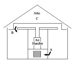
Figure 1. Procedure for determining proportion of return
air coming from attic.
Measure SF6 concentration at near return air grill, (B) at
supply and (C) in attic.
Calculation of infiltration is done with the following formula:
ach = 60/N ln (Ci/Cf)
where N is the number of minutes of the test, C is the initial tracer gas concentration, Cf is the final tracer gas concentration.
This
calculated infiltration is not the true infiltration rate if the air
being drawn into the house has tracer gas concentration greater than
zero because equation 1 assumes that the infiltration air has zero
ppm of tracer gas. Typically we can assume that outdoor air has zero
tracer gas. However, buffer zones such as attics, attached garages,
and crawl spaces may have tracer gas which has come from the house.
When this air enters the house, it does not diminish the tracer gas
concentration as rapidly as if it had rio SF6. This author has measured
attic concentrations as high as 74 % ofthose in the house. In such a
case, equation 1 significantly underestimates the true infiltration
rate. This is an important point for all infiltration tests, especially
those in homes with forced air systems: infiltration rates may be significantly
underestimated in many cases because of tracer gas in buffer zones.
Equation 2 provides an approximate correction to equation 1 when the concentration in the house (A) and in the buffer zone (C) is known, and when it is known that most of the infiltration air is from the buffer zone.
achCORR = ach * (A/A-C))
The basis for Equation 2 can be demonstrated in the following example and discussion.
- True infiltration = 100 CFM
- SF6 concentration in house = 50 PPM (A)
- SF6 concentration in infiltration air stream = 30 PPM (C)
- It can be demonstrated that the decay rate in tracer gas concentration caused by 100 CFM with 50 PPM is equal to the decay that would be produced by 40 CFM infiltration with 0 PPM.
- Equation 2 correctly modifies the calculated infiltrations of 40 CFM to 100 CFM
achCORR = 40 CFM X (50/50-30) = 100 CFM
How does
tracer gas get into the attic and other buffer zones in large quantities?
Obviously this can occur because supply duct leaks spill house air
into the buffer zone. Return leaks can do this by
pressurizing the house, thus forcing house air into adjacent zones.
This author has actually found the highest buffer zone tracer gas concentrations
in homes with large return leaks.
Calculation of Return Leak Fraction
The return leak fraction is calculated from knowing the tracer gas concent’ation in the room at the return grill (A), in thEr supply air stream (B), and in the buffer zone (C) (if the return leak is from a buffer zone). The return leak fraction (RLF) can be calculated from the following formula:
RLF = ((A-B)/(A-C))
Equation 3 is derived by mass balance analysis. In a return leak situation, two streams of air (room and outside) mix together to form a third stream (supply). Each stream has a unique concentration of tracer gas: A in the room, B in the supply stream, and C in the buffer zone where the return leak is occuring. The proportion of air from C (the buffer zone) is termed by the return leak fraction (RLF). The proportion of air from A (the house) is (1- RLF). Therefore, we can write:
RLF (C) + ((1-RLF)(A) = B
Rearranging we can write:
RLF = ((A-B)/(A-C))
If tracer gas measurements are not taken in the buffer zone, then the calculated return leak fraction (setting C = 0,0) can be assumed to be a minimum value; actual RLf is likely to be higher.
This is a very valuable measurement and calculation, because the proportion of return air that is originating outside the house is now known. If the leaks are directly from the outside, or from a buffer zone which has little or no tracer gas, then we know the return leak fraction rather precisely. With this knowledge we can do several things. First, we can compare the return leak fraction to the infiltration rate of the house when the air handler is on. The total air flow rate of the system (measured with an air flow hood) can be multiplied by the RLF to get a return leak air flow rate (RLAFR). The infiltration rate of the house (air changes per hour) can be converted into an air flow rate. If the RLAFR approximately equals the infiltration rate, then the return leak is equal to or larger than the supply leaks. If the infiltration rate is significantly higher than the return leak, and the infiltration rate with the air handler running is considerably higher than the infiltration rate when it is off, then there is a good chance that the supply leaks are approximately equal to the infiltration rate with the air handler on. An important assumption accompanies the above discussion: pressure differences caused by fairly large duct leaks (which we find are quite common) override the pressures of natural infiltration (wind and temperature induced) in most cases. Clearly, this analysis is easier when wind and temperature induced infiltration is .:ia1l, as is common in Florida much of the time.
Second, with this knowledge of the return leak fraction, we can ensure that repair of duct leaks are complete. Upon completion of the repairs, the test can be repeated to see that the return leak fraction has been reduced to zero. If not, then further repairs are indicated. Checking of return leak fraction by itself can be completed in about 15 minutes or less. A complete infiltration test is not needed. A series of four or five return versus supply readings should be sufficient to make an accurate assessment, and these can be done in rapid succession. There is no need to wait 5, 10, or 15 minutes between readings.
Air-Handler-Off Test
Upon completion of the test with the air handler running, the air handler is turned off and readings are taken near the return grill about every 10 minutes for a period of an hour or more. In order to maintain good mixing in the house so that sampling at one location will provide a good approximation of the whole house tracer gas concentration, the air handler is turned on for the last minute of each 10 minute period. Having the air handler on, of course, may increase infiltration above what occurs from wind, temperature, and diffusion affects alone if there are duct leaks. However, since the infiltration rate with the air handler on is known, this can be factored out of the calculated infiltration rate to leave only natural infiltration. As an alternative, fans can be turned on to ensure good mixing throughout the house.
A comparison of the infiltration rate of the house with the air handler on and off will give some indication of significant duct leak problems. The smaller the forces of natural infiltration, the more meaningful will be the comparison. If the natural infiltration rate is say 0.30 ach but jumps up to 1.00 ach when the air handler is running, it is clear that duct leak problems exist. A check of the return leak fraction will indicate whether the problem is in the return system, or only in the supply system. If the return leak fraction is near zero, then it is reasonable to suspect that the supply leak is nearly equal to the infiltration rate. If the return leak fraction is say 20 %, with total air handler air flow rat of 1000 cfm and house volume 12,000 ft , then the return leak can account for the total infiltration rate of 1.0 ach. This does not, however, preclude supply leaks up to the same size as the return leaks.
Infiltration testing both with the air handler on and off has been done by Gammage et al. (1984) (4), Cromer and Cummings (1986) (1), and Cummings (1988,1989) (2), (3) . In samples of 31, 1, 9, and 12 homes, th inf itration rate with the air handlerrunning averaged 80 to 180 percent higher than when the air handler was off.
Conclusions
Tracer gas testing is presented as a diagnostic tool in assessing duct leakage in homes. Two approaches are used. First, a comparison is made between the infiltration rate of the house with the air handler running and when it is off. Secondly, the return leak fraction is determined. This tells rather precisely, in most cases, what fraction of the return air flow is originating outside the conditioned envelope. Smoke sticks and blower doors can be used to locate and measure the duct leak openings. They cannot be used to accurately quantify the duct leak rate. The tracer gas method does not identify the precise location of the leak but does permit quantification of the air leaking from the ducts. From this quantification of the duct leak air flow rate an assessment can be made of the energy impacts upon space conditioning and whether system repair will be cost effective. After repairs have been performed, the tracer gas tests can be repeated to ensure that the leaks, especially return leaks, have been sealed.
References
Cromer, C.J.; Cummings, J.B. 1986. “Field Data Delivery, Interim Report.” FSEC-CR-146-86, Florida Solar Energy Center, Cape Canaveral, Florida, p. 43.
Cummings, J.B. 1988. “Central Air Conditioner Impact Upon Infiltration Ratf in Florida Homes. ‘ Proceedings of the 13 Passive Solar Conference, Cambridge, Massachusetts, p. 135.
Cummings,
J.B.; Tooley, John J. Jr. 1989. “Infiltration Rates and Pressure
Differences in Florida Homes Caused by Closed Interior Doors When
the Central Air Handler is On.” Proceedings of
the 14 Passive Solar Conference, Denver, Colorado.
Gammage, R.B.; Hawthorne, A.R.; White, D.A. 1984. “Parameters Affecting Air Infiltration and Airtightness in Thirty—one East Tennessee Homes.” Measured Air Leakage of Buildings, Philadelphia, Pennsylvania, p. 63.
Acknowledgements
I gratefully acknowledge the assistance of Phillip Fairey, principal research scientist at the Florida Solar Energy Center, in helping to develop these tracer gas test methods. Thanks also go to John Tooley of Natural Florida Retrofit for doing many tests with me and encouraging me to write this paper. Thanks also to Subrato Chandra, Director of Research and Development, Florida Solar Energy Center, for encouraging me to pursue this research.
© 2007-2014 University of Central Florida. The Florida Solar Energy Center (FSEC)
is a research institute of the
University of Central Florida.
For more information about FSEC, please contact us or learn more about us.
Find us on Facebook!