

Reference Publication: McIlvaine, J., Mallette, M., Parker, D., Callahan, M., Lapujade, P., Floyd, D., Schrum, L., Stedman, T., Cumming, B., Maxwell, L., Salamon, M., "Energy-Efficient Design for Florida Educational Facilities," Prepared for the Florida Department of Education, Tallahassee, FL., September, 2000. Disclaimer: The views and opinions expressed in this article are solely those of the authors and are not intended to represent the views and opinions of the Florida Solar Energy Center. |
Energy-Efficient Design for Florida Educational Facilities
Janet McIlvaine, Michele Mallette, Danny Parker, Michael
Callahan, Philippe Lapujade, David Floyd, Lynn Schrum,
Ted Stedman, Brian Cumming, Larry Maxwell, Milt Salamon
Florida
Solar Energy Center (FSEC), R. Douglas Stone Associates, Inc.,
Spacecoast Architects, Technical Editor
FSEC-CR-1682-00
Page 1 | Page 2 | Page 3 | Page 5
In Section III, the design team deals with the largest end-use, HVAC, and often the largest load on that end-use, lighting. During System Design, designers should strive to:
1. Select an efficient lighting system (involving dimming if appropriate).
2.
Select an efficient HVAC system and layout.
Lighting System and Component Selection
A majority of educational facilities use fluorescent lighting in classrooms, offices, conference rooms, libraries, and assembly areas. Each component of a fluorescent lighting system contributes to energy consumption, not just the lamp. Hence, each component should be selected with consideration for its impact on the energy consumption of the overall system. The primary reason for selecting an improved lighting system is increased lamp-ballast efficacy which can lead to reduced energy consumption, and consequently less heat production. System efficacy is the ratio of system output (in lumens) to system input (in watts). An improved system will either produce more lumens for the same power input or the same lumens with less power input.
Keep in mind that part of the savings achieved by more efficient lighting comes from the reduction of heat generated by the lights. As a rule of thumb, approximately 1 watt of increased HVAC electrical consumption accrues for every 4 watts of electricity consumed by lighting. Therefore, if the energy consumption of a luminaire can be reduced by 40 watts a total savings of 50 watts will be achieved (40 watts light savings + 10 watts HVAC savings). All of the electricity consumed by the lighting system gets converted either directly into heat or first into light and then into heat. With less power being supplied to the lights, less total heat is produced.
Lighting assemblies: Elements of a lighting system affect each other, so a combination of lighting components may behave differently than the components do separately. To account for this the data used to model these configurations was taken from lighting system experiments performed by FSEC.
These studies, performed at the Florida Solar Energy Center, document
energy consumption, work surface illumination, power factor, lamp wall
temperature, and a variety of other parameters for 39 lamp-ballast-fixture
combinations (Parker, Stedman and Sonne, 1994).
HVAC System and Component Selection
The principal job of the HVAC system in Florida is to provide comfortable space conditions for a learning environment and to provide adequate ventilation of outside air for building occupants. The HVAC system must deal with all the heat and moisture transmitted by the building envelope (external gains) and all the heat and moisture produced by occupants, lights, equipment, and processes (internal gains). By implementing the measures in Schematic Design, Design Development, and Systems Design to limit both external and internal gains, designers can expect lower sensible air conditioning loads. However, lowering sensible cooling loads will lower sensible heat ratios (SHR) necessary from HVAC equipment and challenge the designer. Space conditions will be more difficult to meet without the use of reheat systems, and room air motion may be reduced with variable air volume (VAV) systems.
Once loads have been reduced as much as possible, select a system appropriate for the facility and then choose the most efficient model available in each equipment category. High-efficiency motors may be added for fans and variable speed pump drives for variable volume systems. Careful attention should be paid to effectively meeting building ventilation requirements while providing sufficient dehumidification of outdoor air prior to its introduction to the interior environment.
To achieve successful HVAC design, the architectural members of the design team must closely communicate with the engineering members. If special efforts have been made to reduce the air conditioning load in the Schematic Design and Design Development phases, and no one informs the mechanical engineer, the building may not get the proper size cooling system. An oversized system will not run at maximum efficiency. On the other hand, the mechanical engineering members of the design team should feel free to make suggestions on how to decrease the HVAC load during design development. The nature of energy-efficient design requires communication and cooperation among members of different design disciplines working toward the same goal.
Strategies for System Design
| Energy Intensity | Energy Cost | Cooling Capacity | Electric Consumption | Gas Consumption |
Incremental First Cost | Energy Cost Savings | Simple Payback | ||
| Classroom Building | kBTU/sqft | $ | Tons | kWh | Therms | $ | $ | Years | |
| 30 | F40, T12, magnetic ballast | 45 | 16,058 | 47 | 193,231 | 99 | 6000 | -577 | -10 |
| 31 | F34, T12, magnetic Ballast, open diffuser, parabolic troffer | 43 | 15,383 | 46 | 185,072 | 104 | 0 | 98 | 0 |
| 32 | F34, T12, electronic ballast | 40 | 14,330 | 45 | 165,414 | 118 | 3200 | 1151 | 3 |
| 33 | F32, T8, electronic ballast | 39 | 13,854 | 44 | 166,570 | 117 | 9700 | 1627 | 6 |
| 34 | High-Efficiency exit sign | 43 | 15,291 | 46 | 183,944 | 105 | 900 | 190 | 5 |
| 61 | Occupancy sensors | 41 | 14,492 | 45 | 174,067 | 112 | 720 | 989 | 1 |
| 7 | 32W, T-8, continuously dimming electronic ballast | 36 | 12,936 | 42 | 154,017 | 121 | 5400 | 2545 | 2 |
| 45 | 15 CFM per person | 48 | 17,259 | 59 | 204,413 | 129 | * | -1778 | 0 |
| 46 | TERS 5 CFM per person | 42 | 16,848 | 45 | 180,873 | 94 | 18,800 | -1367 | -14 |
| 47 | TERS 15 CFM per person (compared to #45) | 47 | 17,165 | 59 | 203,664 | 0 | * | -1684 | 0 |
| 48 | Optimal start | 41 | 15,019 | 46 | 178,288 | 64 | 5000 | 462 | 11 |
| 49 | Enthalpy economizer | 43 | 15,462 | 46 | 185,909 | 104 | 0 | 19 | 0 |
| 51 | Reheat constant volume | 43 | 15,264 | 47 | 184,056 | 103 | * | 217 | 0 |
| 35 | Centrifugal chiller | 39 | 13,508 | 47 | 164,311 | 103 | * | 1973 | 0 |
| 36 | Screw chiller | 35 | 12,686 | 47 | 151,681 | 86 | 2400 | 2795 | 1 |
| 37 | Gas absorption chiller | 81 | 12,970 | 47 | 127,471 | 7654 | * | 2511 | 0 |
| 38 | Ceiling Fans |
33 |
10,276 |
44 |
185,771 |
86 |
3000 |
5205 |
1 |
| 39 | Variable speed pumps | 43 | 15,237 | 47 | 182,607 | 97 | * | 244 | 0 |
| 40 | Non-Variable speed fans | 46 | 22,686 | 47 | 194,949 | 99 | * | -7205 | 0 |
| 41 | Variable temperature constant volume | 42 | 15,230 | 46 | 182,307 | 31 | * | 251 | 0 |
| 42 | Multizone constant volume | 41 | 14,754 | 45 | 179,033 | 41 | 11 | 726 | 0 |
| 43 | Dual duct constant volume or variable volume | 42 | 15,195 | 46 | 183,460 | 35 | * | 285 | 0 |
| 44 | Four pipe fan coil | 34 | 11,926 | 39 | 146,562 | 83 | * | 3555 | 0 |
| 52 | Unitary heat pumps | 42 | 20,802 | 47 | 183,673 | 4 | * | -5321 | 0 |
| 53 | Packaged single zone variable temp DX unit | 37 | 14,163 | 39 | 161,450 | 0 | * | 1318 | 0 |
| 54 | Packaged multizone DX unit | 37 | 13,430 | 38 | 160,551 | 0 | * | 2051 | 0 |
* Data not available: Price varies too widely to approximate
| Energy Intensity | Energy Cost | Cooling Capacity | Electric Consumption | Gas
Consumption |
Incremental First Cost | Energy Cost Savings | Simple Payback | ||
| Administration Building | kBTU/sqft | $ | Tons | kWh | Therms | $ | $ | Years | |
| 30 | F40, T12, magnetic ballast | 44 | 10,132 | 25 | 127,436 | 56 | 4050 | -398 | -10 |
| 31 | F34, T12, magnetic Ballast, open diffuser, parabolic troffer | 42 | 9668 | 25 | 121,872 | 61 | 4050 | 67 | 60 |
| 32 | F34, T12, electronic ballast | 39 | 8950 | 24 | 108,546 | 74 | 2160 | 785 | 3 |
| 33 | F32, T8, electronic ballast | 38 | 8624 | 23 | 109,341 | 73 | 6548 | 1110 | 6 |
| 34 | High-Efficiency exit sign | 42 | 9610 | 25 | 121,148 | 62 | 900 | 125 | 7 |
| 61 | Occupancy sensors | 41 | 9338 | 25 | 114,421 | 68 | 720 | 397 | 2 |
| 7 | 32W, T-8, continuously dimming electronic ballast | 35 | 8033 | 22 | 100,663 | 77 | 3645 | 1702 | 2 |
| 45 | 15 CFM per person | 45 | 10,412 | 27 | 129,904 | 75 | * | -677 | 0 |
| 46 | TERS 5 CFM per person | 42 | 9583 | 24 | 120,888 | 59 | 10,000 | 152 | 66 |
| 47 | TERS 15 CFM per person (compared to #45) | 43 | 10,124 | 28 | 126,969 | 0 | * | -389 | 0 |
| 48 | Optimal start | 42 | 9627 | 25 | 119,139 | 39 | 5000 | 108 | 46 |
| 49 | Enthalpy economizer | 42 | 9715 | 25 | 122,309 | 62 | 2400 | 20 | 122 |
| 51 | Reheat constant volume | 42 | 9614 | 25 | 121,439 | 60 | * | 121 | 0 |
| 35 | Centrifugal chiller | 39 | 8726 | 25 | 111,533 | 60 | * | 1008 | 0 |
| 36 | Screw chiller | 37 | 8656 | 25 | 104,658 | 51 | 2400 | 1079 | 2 |
| 37 | Gas absorption chiller | 117 | 12,400 | 47 | 121,069 | 7560 | * | -2665 | 0 |
| 39 | Variable speed pumps | 42 | 9634 | 25 | 120,680 | 57 | 3000 | 101 | 30 |
| 40 | Non-Variable speed fans | 44 | 14,200 | 25 | 127,275 | 60 | * | -4465 | 0 |
| 41 | Variable temperature constant volume | 41 | 9395 | 24 | 119,839 | 36 | * | 340 | 0 |
| 42 | Multizone constant volume | 41 | 9336 | 24 | 118,703 | 10 | * | 399 | 0 |
| 43 | Dual duct constant volume or variable volume | 41 | 9598 | 24 | 121,376 | 5 | * | 136 | 0 |
| 44 | Four pipe fan coil | 35 | 7762 | 20 | 100,892 | 41 | * | 1972 | 0 |
| 52 | Unitary heat pumps | 42 | 9722 | 25 | 121,312 | 18 | * | 13 | 0 |
| 53 | Packaged single zone variable temp DX unit | 37 | 8980 | 20 | 109,230 | 0 | * | 755 | 0 |
| 54 | Packaged multizone DX unit | 37 | 8549 | 20 | 108,769 | 0 | * | 1186 | 0 |
| 55 | Package terminal AC / heat pump | 37 | 9090 | 109,064 | 0 | * | 644 | 0 | |
* Data not available: Price varies too widely to approximate
| Energy Intensity | Energy Cost | Cooling Capacity | Electric Consumption | Gas Consumption | Incremental First Cost | Energy Cost Savings | Simple Payback | ||
| Multipurpose Building | kBTU/sqft | $ | Tons | kWh | Therms | $ | $ | Years | |
| 31 | F34, T12, magnetic Ballast, open diffuser, parabolic troffer | 16.12 | 4055.05 | 22 | 507,539 | 419.86 | 5385 | 14 | 0 |
| 32 | F34, T12, electronic ballast | 15.75 | 3911.23 | 20 | 490,111 | 429.69 | 2872 | 157 | 0 |
| 33 | F32, T8, electronic ballast | 15.58 | 3846.25 | 20 | 482,192 | 434.24 | 8706 | 222 | 0 |
| 34 | High-Efficiency exit sign | 16.07 | 4039.56 | 20 | 505,699 | 420.32 | 320 | 29 | 11 |
| 7 | 32W, T-8, continuously dimming electronic ballast | 15.32 | 3730.18 | 20 | 471,362 | 437.12 | 4847 | 338 | 14 |
| 45 | 15 CFM per person | 21.36 | 5864.06 | 34 | 689,505 | 498.94 | * | -1795 | 0 |
| 46 | TERS 5 CFM per person | 14.86 | 3595.91 | 17 | 460,923 | 410.51 | 8000 | 473 | 0 |
| 47 | TERS 15 CFM per person (compared to #45) | 16.13 | 4067.08 | 20 | 509,121 | 415.86 | 8000 | 2 | 0 |
| 48 | Optimal start | 14.91 | 3902.62 | 20 | 487,187 | 328.5 | 5000 | 166 | 0 |
| 49 | Enthalpy economizer | 16.12 | 4059.39 | 20 | 507,419 | 420.69 | 2400 | 9 | 0 |
| 51 | Reheat constant volume | 16.00 | 4007.71 | 20 | 503,035 | 419.09 | * | 61 | 0 |
| 35 | Centrifugal chiller | 3370.3 | 4698 | 20 | 438,509 | 418.93 | * | -629 | 0 |
| 36 | Screw chiller | 2563.3 | 3566 | 20 | 383,276 | 356.82 | 2400 | 502 | 0 |
| 37 | Gas absorption chiller | 3074.7 | 3833 | 20 | 298,421 | 3110.5 | * | 235 | 0 |
| 39 | Variable speed pumps | 3935.8 | 5500 | 20 | 490,873 | 403.77 | 3000 | -1431 | 0 |
| 40 | Non-Variable speed fans | 4544.4 | 6359 | 20 | 578,936 | 415.62 | * | -2290 | 0 |
| 41 | Variable temperature constant volume | 13.77 | 4008.28 | 20 | 513,076 | 87.25 | * | 60 | 0 |
| 42 | Multizone constant volume | 13.16 | 3690.1 | 19 | 480,097 | 119.1 | * | 379 | 0 |
| 43 | Dual duct constant volume or variable volume | 13.41 | 3810.93 | 20 | 493,317 | 106.81 | * | 258 | 0 |
| 44 | Four pipe fan coil | 10.99 | 2554.21 | 16 | 337,521 | 315.35 | * | 1514 | 0 |
| 52 | Unitary heat pumps | 13.68 | 4051.14 | 18 | 494,644 | 138.79 | * | 17 | 0 |
| 53 | Packaged single zone variable temp DX unit | 11.99 | 3947.03 | 20 | 468,925 | 0 | * | 122 | 0 |
| 54 | Packaged multizone DX unit | 10.98 | 3532.28 | 20 | 429,487 | 0 | * | 536 | 0 |
| 55 | Packaged terminal AC / heat pump | 11.70 | 4223.14 | 17 | 457,838 | 0 | * | -155 | 0 |
* Data not available: price
varies too widely to approximate.
Strategy:
Efficient Electrical Lighting.
Objective: Provide superior electrical illumination with reliable systems that require less power and produce less heat than standard practice systems.
Considerations: Electrical lighting impacts building energy use in two ways. First, energy consumed by lights constitutes a major portion (32%) of overall building consumption. Second, all power consumed by lighting systems is eventually converted into heat. This makes up a sizable portion of the air conditioning sensible load in school buildings.
Design teams have three options for reducing general lighting power consumption. First, select more efficient system components such as ballasts, lamps, lenses, and troffers. With this strategy, strive to achieve the highest lumen output per watt input, or efficacy, for the fixture as a unit. Second, provide occupancy sensors, time clocks, or some other automatic or manual controls that limit the length of time the lighting system operates. Third, provide mechanisms to dim electrical lighting when sufficient natural lighting is present.
Providing adequate lighting must always remain a top priority when considering any innovative lighting systems since the quality and quantity of light directly impacts the comfort and productivity of the students and instructors.
ECM Options:
1. Efficient System Components
a. Ballasts
b. Lamps
c. Fixtures
d. Ambient and Task Lighting
e. Exit Signs
2. Automated Lighting Controls
a. Occupancy Sensors
b. Continuously Dimming Electronic Ballasts
3. Consensus Recommendations
1. Efficient System Components for General Lighting
Designers have many new options for increasing the lamp-ballast efficacy. The following descriptions serve as an introduction to some of the alternative products to standard 34 watt, T-12, energy efficient magnetic ballast configuration used in the base case simulation.
a. Ballasts
Designers have three basic options for operating fluorescent lamps. The energy-efficient magnetic ballast, the cathode cutout ballasts, and the high-frequency electronic ballast. The dimming electronic ballasts will be discussed later.
The energy-efficient magnetic ballast uses less energy than a standard core-coil ballast because copper wire is used instead of aluminum wire. Until the 1990s most ballasts sold in America today were energy-efficient magnetic ballasts; however, the current trend is moving toward electronic ballasts. Cathode cutout ballasts combine magnetic components with electronic switching circuits to remove filament power after the ballast has performed its start-up duty. This improves system efficacy by about 5% but may reduce lamp life. The high-frequency electronic ballast converts the 60 Hz line voltage supply into high frequency (above 20 kHz) power. This high frequency power serves the same purpose as the 60Hz power that magnetic ballasts produce: it excites an arc in the lamp to make light. However, fluorescent lamps have been shown to operate at a 10% to 15% higher efficacy with high frequency input (LRC Specifier Reports) which the electronic ballast can supply (Figure 27).
Figure 27. Magnetic ballasts (top) transmit
60 Hz line voltage to fluorescent lamps whereas electronic ballasts (bottom)
provide high frequency (20-40 Hz) to fluorescent lamps yielding 10% to 15%
higher efficacy.
Electronic ballasts are available for T-12, T-10, and T-8 lamps and can be used with almost any fluorescent fixture or housing. Electronic ballasts also consume less energy and run cooler than the magnetic type, resulting in about a 10% reduction in ballast losses. Additionally, electronic ballasts can produce minimal harmonics, meaning quieter operation and less interference with other electrical devices.
A single electronic ballast can run between one and four lamps as opposed to only two lamps for magnetic ballasts. This lends great flexibility to lighting design and can reduce the number of required ballasts. Lamp output, however, changes slightly with each incremental increase in the number of lamps per ballast. The factor that determines how much of the maximum light a lamp actually produces is called ballast factor (i.e., a lamp rated at 3050 lumens driven on a ballast with a ballast factor of 0.95 will only produce 2900 lumens). Ballast factors greater than 1.00 will decrease lamp life.
Both rapid-start and instant-start types offer savings; however, the instant-start ballasts, which respond immediately when switched, may shorten lamp life because they keep the lamps in a constant "ready" state.
Although some manufacturers estimate that their electronic ballasts will last 20 years, the average life of an electronic ballast is unknown. Careful consideration should be given to warranty (available up to 5 years) and historical performance of a particular model.
Design teams should avoid coupling electronic ballasts with power line carrier (PLC) type energy management systems due to possible interference.
Other important characteristics to consider are surge protection, power quality (THD less than 20%), crest factor (less than 1.7), and power factor. In retrofit applications the power company should be consulted regarding financial incentives and minimum requirements for electronic ballasts. For example, electronic-magnetic hybrid ballasts may offer excellent efficiency and quality for utility rebates, yet cost less than a fully electronic ballast. Similarly, lower THD ballasts will usually cost more than high THD ballasts. The power company may recommend or require THD be less than a specified value to qualify for the rebate. A target THD of 20% is reasonable. Values significantly higher than this may cause harmonic related disturbances in the electric system, such as transformer or neutral conductor heating.
The potential for electric surge damage to electronic ballasts is not fully understood. However, it is recommended that at least two stages of building power system surge protection be installed in front of the lighting ballast branch circuits.
b. Lamps
Lamp efficacy (Figure 28) and the configuration of lamps in a fixture have great impact on the efficacy of the fixture as a whole. Three sizes of lamps are now available: T-12 (1½-inch diameter), T-10 (1¼-inch diameter), and T-8 (1" diameter). The T-12 lamp in two or four lamp fixtures with energy-efficient, magnetic ballasts has the lowest first-cost and is the most common choice; however, the efficacy of this configuration falls below many other configurations available today.
Figure 28. Luminous efficacy, light out-put
in lumens per power input in watts, for various lamps.
The T-10 lamp commonly replaces the T-12 in retrofit applications because it can be used with the same magnetic ballast as the T-12 lamp. The T-10 offers a higher efficacy (higher light output for the same amount of power input), which means that the number of lamps per fixture can often be decreased while maintaining the same light level. With fewer lamps housed in a fixture, less light is trapped in the top part of the troffer, increasing the efficacy of the fixture. Unfortunately, T-10 lamps are currently over three times as expensive a T-12 lamps and they place greater loads on the ballasts, which could result in ballast failures in older retrofit applications.
The T-8 lamp is recommended for both new and retrofit applications; however it requires a compatible ballast. These smaller lamps do not require any different kind of wiring techniques, and they offer many advantages over standard T-12 lamps. They have higher efficacy (lumens/watt) and trap less light in the fixture than the larger diameter T-12 lamps, increasing the efficacy of the luminaire. T-8 lamps with electronic ballasts, which operate at a higher frequency than magnetic ballasts, have no perceivable flicker. They also offer improved color rendering compared to the standard, cool-white T-12 lamps resulting in improved visual quality.
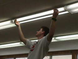
Figure 29. Lighting retrofit in a classroom. T12 lamp magnetic ballast
system was replaced by a T8 electronic ballast system.
 |
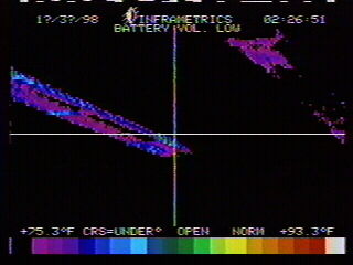 |
Figure 30. Infrared thermographs of the T12 lamp magnetic ballast (left) and T8 lamp electronic ballast (right) lighting systems. The temperature range is 75o - 93o F. In the thermographs, color is proportional to temperature with white the hottest and violet the coolest. The T8 electronic ballast system runs much cooler.
c. Fixtures
Standard fluorescent luminaires house between one and four lamps in a rectangular troffer with prismatic diffuser. The conventional design of these fixtures limits the amount of light that actually is distributed. A portion of the light from the top of the lamps projects up and reflects back down off the troffer top but never makes it past the lamps. This light bounces around in the corners of the fixture and is blocked by the lamps themselves. The problem can be avoided by either allowing more free space around the lamps (less lamps per fixture) or by using specular reflectors that more effectively redirect light from the top of the lamps.
Specular reflectors not only reshape the interior of the luminaire, but offer an increase in fixture efficacy as well. They can work very well in older fixtures where reflective paint has yellowed due to age. Often a two-lamp regular or high output T-8 luminaire with reflectors can be substituted for a standard four-lamp T-12 fixture. This configuration will have an increased first cost but the energy savings and lamp replacement cost saving should offset this quickly. Tandem wiring of four-lamp ballast to two two-lamp luminaires can offset this first cost substantially and increase system performance.
An alternative to prismatic diffusers is a parabolic louver. Parabolic louvers are open grids (Figure 31 and 32) that transmit light in a different way from prismatic diffusers. The grid spacing varies from half an inch to several inches. As a general rule the efficacy of the fixture decreases directly with the cell size of the grid. Parabolic louvers tend to have a higher visual comfort probability but are not as efficient at light distribution as the prismatic diffuser. The parabolic louvers project light directly below the fixture in a distinct cone pattern whereas the prismatic diffusers throw light in all directions. Parabolic louvers are most appropriate for rooms with computers and video display terminals (VDTs) since they cause less disability glare than prismatic diffusers. One advantage of the parabolic louvers is that they do not trap heat in the fixture as do prismatic diffusers. This lowers the lamp wall temperature. Fluorescent lamps operate optimally when lamp wall temperature is about 100oF. Prismatic diffusers can cause cathode end temperatures to climb above this optimal temperature, causing reductions in lamp efficacy.
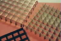
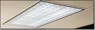
Figure 31. Parabolic louvers to enhance
light distribution.
Figure 32. Standard prismatic diffusers
(top) throw light in all directions whereas parabolic diffusers (bottom) project
light directly below the fixture.
d. Ambient and Task Lighting
Compact fluorescent lamps (Figure 33) offer many advantages over incandescent lamps and are used widely
for task lighting. Compact fluorescent lamps are available in a wide range
of sizes and configurations. They last about ten times as long as incandescent
lamps and some offer excellent color rendering. A 13-watt compact fluorescent
lamp provides about the same illumination as a 60-watt incandescent lamp
and produces considerably less heat. This characteristic offers extra appeal
for task lighting since the heat generated by task lighting warms the user's
immediate work area above that of the rest of the space.
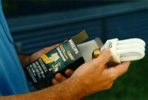
Figure 33. Compact fluorescent lighting such as recommended for use
in task lighting. These easily substitute for standard incandescent lamps.
One effective strategy used in VDT offices is to combine low ambient light levels (30 footcandles) with a small task light to use for reading and writing. This may not be practical in a classroom setting, however.
e. Exit Signs
Exit signs operate 24 hours a day, 365 days a year. In a typical building having six to eight signs, this constitutes a significant cumulative energy use. Several options to incandescent exit fixtures offer less energy consumption and lower maintenance. Electroluminescent exit signs use no power and last for up to 20 years. They require no wiring and virtually no maintenance. LED exit signs and fluorescent exit signs (Figure 34) also offer large savings with little maintenance and both cost less than electroluminescents. They use standard wiring and have a long life expectancy. The LEDs have a projected life ranging from 700,000 to over 5 million hours, but the standby battery must be replaced every 80,000 hours. The fluorescent fixtures have a life of about 15,000 hours. Although, they make up only a small fraction of the building lighting load, use of LED or flourescent exit signs was found to be very cost effective (Figure 35).

Figure 34. LED exit signs
|
|
|

| 9 No Electrical Lighting 30 F40, T12, Magnetic Ballast 31 F34, T12, Mag. Ballast, Open Diffuser, Parabolic Troffer 32 F34, T12, Electronic Ballast 33 F32, T8, Electronic Ballast 34 High-Efficiency Exit Sign |
Figure 35. Reducing electrical lighting reaps a large saving because lights both consume electricity and produce heat. Electronic ballasts coupled with either T-12 or T-8 lamps produced impressive savings.
2. Automated Lighting Controls
Simply turning off the lights in unoccupied rooms is good conservation practice. The possible exception would be spaces where lights serve another purpose, such as to maintain safety or security (egress hallways for night school classes), to imply that visitors may enter a space (lights in the library on open house night), to maintain light in spaces where occupants aren't moving much (reading or study rooms) or with fixtures that require a warm-up time (gymnasium HID lights). So, for the sake of such circumstances, an override switch for automated lighting controls should be provided along with clear guidelines about appropriate times to use the override.
a. Occupancy Sensors
Occupancy sensors are electrically powered controls which may replace the light switches in small rooms such as offices or be placed in the ceiling for more accurate control in large areas such as classrooms and conference rooms. They detect changes in the environment in one of two ways. Passive infrared (PIR) sensors see a heat image in a space and turn lights off when the image remains constant for a specified period. Ultrasonic sensors send and receive sound waves. They detect changes in the sound image of the space and turn lights off when the image has been constant for a specified time. The time delay prior to automatic switching can be adjusted for occupancy sensors. Depending on the manufacturer ranges are available from three seconds to 30 minutes. Some units use both sensing methods to reduce the chance of false readings (Figure 36). Proper commissioning of occupancy sensors in terms of time delay settings and sensitivity is essential for user acceptance and should be an integral part of project specifications to ensure proper performance.
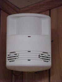
Figure 36. Occupancy sensor (combination ultrasonic/infrared).
The type and manufacturer of a sensor determine the physical range of detection (size of the heat or sound image) and manufacturer information should be reviewed to find the appropriate sensor for each space. Manufacturers will provide layouts free of charge. For small spaces, such as copy rooms, conference rooms, and offices, one sensor will likely be adequate. Multiple sensors will provide better control for large open spaces such as auditoriums. Payback is fastest in seldom used areas with multiple fixtures such as conference rooms.
Spaces likely to reap the greatest benefits are common areas. These include copy rooms, break rooms, conference rooms, mail rooms, supply rooms, bathrooms, reading rooms, media rooms, community work rooms, etc., may be inappropriately lit all day because no one has thought about turning off the lights or because "We always leave them on." Occupancy sensors will even benefit spaces such as offices and classrooms where occupants leave the room during the course of the day and return much later, or not at all.
After everyone has left the building for the day, occupancy sensors ensure that the lights will be turned off. Energy management systems also offer this capability, but at a much higher cost. Occupancy sensors can also provide a security alert. If police know that a school should be dark at night, lights will help signal a possible intrusion.
Research experience at Northwest Elementary, a school in Pasco County, has demonstrated savings of 10.2% (96.8 kWh/school day) in lighting. Pasco County schools, generally, are very diligent in turning off lights when instructors leave classrooms, cafeterias are not in use, and cleaning crews finish for the evening, so these savings could potentially be greater in schools that don't practice energy efficiency as diligently as Pasco County does. When cooling energy use is also included in the analysis, the yearly savings were calculated to be approximately 26,620 kWh (19,360 kWh for lighting; 7,260 kWh for cooling loads). The annual estimated savings were $1,694 with a simple payback of 3.6 years (28% rate of return from investment). Most of the savings took place during the evening hours so that the monthly demand charges would be unaffected (Floyd et al, 1995).
b. Continuously Dimming Electronic Ballasts
Ballasts with dimming capability can play a significant role in the success of a daylighting plan. No amount of glazing design and layout can ensure the success of a daylighting strategy if the electric light output can not be reduced. There are two ways this can be accomplished. One is to reduce light fixture density in daylit perimeter zones and by windows or skylights. Another is to use automatic dimming controls when natural light meets or exceeds the desired lighting levels. Electronic dimming ballasts reduce power consumption and light output either in distinct steps or continuously over the full range of rated output. Generally, continuously dimming controls are preferred to stepped controls due to greater occupant acceptance of the continuous systems.
Magnetic ballasts can be configured to dim in response to daylighting using autotransformers or other wave chopping techniques, but only down to about 40% of light output before flickering becomes pronounced. These are not recommended.
Electronic ballasts have no perceivable flicker, even when dimmed down as low as 5% of output because of the high frequency of the input current. Additionally, the electronic ballasts offer higher efficiencies at reduced power.
Continuously dimming electronic ballasts work in conjunction with a photometric light sensor which is mounted on the ceiling. The photometric sensor sends an electronic signal (DC voltage) to the ballast, which actually controls the light output level, reducing power to the lamps when ambient light levels are sufficient. Some sensors feature a potentiometer that can be calibrated to adjust the dimming range. After installation, a technician adjusts the potentiometer to dim when the light level (measured at the work plane, not the ceiling) meets the desired level for the occupants. In general, it is recommended that project specifications for daylighting projects with dimming controls include requirements for system commissioning. This will insure proper function of the daylighting control system and sufficient lighting levels during nighttime hours. A Florida Department of Education project at Read Patillo Elementary showed that a 27% reduction in lighting energy use was demonstrated due to the use of a daylight dimming system. Implementation in classrooms designed for daylighting should produce savings of 50% or more.
Some manufacturers produce dimming sensors that can control multiple ballasts, which reduces first costs. But with fewer fixtures per sensor, a more accurate light level will be measured for the area each fixture is actually illuminating. One method of configuring dimming controls places a single sensor for each bank of light fixtures in adjacent spaces that receive the same daylight exposure. This configuration must be provided with override controls for individual rooms to allow for projection activities and occupancy variations. Additionally, it makes no allowances for individual room conditions such as uneven shading. Unless rooms are identical in all aspects, this configuration may cause undue discomfort in some parts of the zones. A more expensive method provides one sensor per ballast, yielding superior accuracy in daylight dimming light in a specific space. A compromise with a single light sensor controlling a bank of similarly located lamps is often the best choice.
Remember that all the ballasts connected to a sensor will dim according to the light level at the point of the sensor, regardless of the actual light level below the lamp. For classrooms with rows of lighting parallel to windows, consider one central sensor per row or two sensors per row of dimmable fixtures for an adequate response to available natural lighting (Figure 37).
|
|
| 61 Occupancy Sensors 7 32W, T-8, Continuously Dimming Electronic Ballast |
Figure 37. Reducing the run time of the lighting system yields two rewards: reduced electrical consumption and reduced heat generation. Occupancy sensor savings shown here are a conservative estimate based on empirical data for conducted research. Continuously dimming electronic ballasts automatically dim lights to strike a balance between electrical and natural lighting that meets lighting requirements. They are, however, only one component of a daylighting plan.
In consideration of circuitry, the daylit space should be divided into several zones. Zones not near daylighting apertures may receive very little if any natural light, and hence will not benefit from dimming capability. The depth of a daylight zone, and consequently the number of rows of fixtures benefitting from dimming ballasts depends on the design of windows and exterior shading. Use of available computer software can aid in predicting available daylight at different points in a space at different times of the year.
Choose an efficient combination of lamps, ballasts, diffusers and troffers for the facility lighting system. The use of T-8 lamps with an electronic ballast and an appropriate luminaire is are increasingly used and are preferred in all cases. Research in a pair of portable classrooms in Volusia County has shown that T8 lamp electronic ballast lighting system saved 35% in energy use over the typical T12 lamp magnetic ballast lighting system (Callahan et al 1999).
Consider lower ambient interior lighting levels with task lighting for non-classroom spaces with heavy use of video display terminals (VDTs).
Specify fluorescent or LED type exit sign lighting.
Use occupancy sensors to control spaces with changing occupancy. Specify that such controls will be commissioned such that time delays are properly set and device sensitivity is adjusted. Based on two retrofit projects, while bathrooms and hallways are good choices, classrooms may not be. In any case, lighting energy savings from occupancy sensor use in classrooms cannot be expected to be greater than 10%. If coupled with control of HVAC systems in portable classrooms, however, savings may be very attractive.
Use continuously dimming electronic ballasts with photosensors to control electric lighting in daylit zones or reduce the light fixture density in perimeter daylight zones. Specify that such systems be commissioned to ensure that controls function properly and light levels are adequate during non-daylit hours.
© 2007-2014 University of Central Florida. The Florida Solar Energy Center (FSEC)
is a research institute of the
University of Central Florida.
For more information about FSEC, please contact us or learn more about us.
Find us on Facebook!