

Reference Publication: Cummings, James. B. and Charles R. Withers, "Best Practice for the Location of Air and Thermal Boundaries in Small Commercial Buildings", Proceedings of 12th Annual Symposium on Improving Building Systems in Hot and Humid Climates, San Antonio, TX, May 2000. Disclaimer: The views and opinions expressed in this article are solely those of the authors and are not intended to represent the views and opinions of the Florida Solar Energy Center. |
Best
Practice for the Location of the Air and Thermal
Boundaries in Small
Commercial Buildings
James
B. Cummingsand Charles
R. Withers
Florida
Solar Energy Center (FSEC)
FSEC-CR-1667-00
Abstract
Suspended t-bar ceilings are common in commercial buildings. Research has found that these ceilings are very leaky, and several problems arise from this. If the space above the ceiling is vented to outdoors, the entire building becomes leaky. Furthermore, if the insulation is located at the ceiling rather than the roof, then the ceiling space will be hot (summer), and if the ceiling space is also vented to outdoors, then the ceiling space will be hot and humid. The thermal and humidity conditions of the ceiling space have important implications for space conditioning loads, building ventilation rates, and indoor relative humidity. Conductive gains through ductwork add to loads, and various forms of uncontrolled air flow readily move air between the ceiling space and the occupied space. These factors should be considered during design and construction of commercial buildings. Best practice: locate the air and thermal boundaries of the building at the roof deck. This approach has many benefits.
Introduction
Suspended t-bar ceilings are ubiquitous in commercial buildings. In a study of small commercial buildings, 57 of 69 buildings had suspended t-bar ceilings (Cummings et. al., 1996). Testing has found that these suspended ceilings are not airtight, and this is because of cracks on all four sides of each ceiling tile and other openings and gaps. Based on direct testing of ceiling airtightness in two buildings, it has been found that these ceilings have a tightness of approximately 5.0 cfm (2.4 L/s) of air flow per square foot at 0.20 inWC (50 pascals) pressure differential, making them about 10 times more leaky than gypsum board ceilings (Cummings et. al., 1996). Testing of total building airtightness in 69 buildings points to the same conclusion (see following "Current Practice" section).
Building design often does not take into account the airtightness characteristics of suspended t-bar (STB) ceilings. Design and construction often treats the STB ceiling as if it were a reasonably airtight boundary, when in fact it is not. This has several consequences; 1) the air boundary of the building envelope is often much leakier than expected, 2) air moves to and from places that were unintended, and 3) the building envelope cannot contain a significant pressure field.
Current Practice
Airtightness testing was performed in 69 small commercial buildings located in central Florida (Cummings et. al., 1996). Figure 1 presents the data in airtightness bins. It was found that a significant minority of the 69 buildings are quite airtight, with 42% having an airtightness of 10 or less air changes per hour at 50 pascals (ACH50). On the other hand, 38% of the tested buildings had ACH50 greater than 20. The distribution is bi-polar, with a strong peak at 5 to 10 ACH50 and another pronounced peak at 20 to 25 ACH50. This distribution suggests a single variable which, like a switch, is either "on" or "off". That switch, as it turns out, is related to STB ceilings. If the ceiling is STB and the space above the ceiling is vented to outdoors, then the building will be leaky; more on that later.
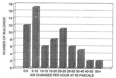
Figure 1 Airtightness of 69 Central Florida Small Commercial Buildings
When analyzed by age, there is a general trend of increasing airtightness for newer buildings, with the exception that those built 30 to 40 years ago are the most airtight (Figure 2). Comparison to single family homes is instructive. Single family residences (in central Florida) are also becoming more airtight over time (Figure 3), but the pattern is more clear and consistent for residences compared to small commercial buildings. While older single family homes (40+ years) are approximately equal in leakiness to older small commercial buildings, new single family homes are much tighter than new small commercial buildings. Residences built in the ten years ending in 1990 are much tighter (6 ACH50) than small commercial buildings constructed in the ten years ending in 1996 (14 ACH50). For both residential and small commercial buildings in central Florida, the slab-on-grade floor is tight, and the walls, windows, and doors are generally tight. The primary difference lies in the fact that residences do not use STB ceilings, but small commercial buildings do.
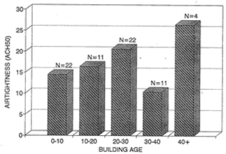
Figure 2 Airtightness vs. Age in Central Florida Commercial Buildings
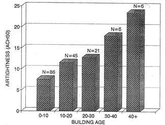
Figure 3 House Airtightness vs. Age
Eight Ceiling Space Configurations
As indicated, more than 80% of the tested small commercial buildings have STB ceilings. However, the presence of a STB ceiling is not in itself a sufficient factor to cause the building to be leaky. Figure 4 subdivides the 69 tested buildings into 8 construction categories, based on the type of ceiling, the location of insulation, and whether the ceiling space or attic space is ventilated. Configuration 1 has no ceiling and configuration 8 has a tight ceiling (gypsum board). The other six configurations mostly have STB ceilings. At the top of each "building" in Figure 4 is the average ACH50 for the sample, and the sample size is indicted by "n = xx".
Following are descriptions of the natural summer temperature and humidity conditions in the ceiling space for the building configurations. "Natural" conditions refers to the conditions that will result in the ceiling space in the absence of uncontrolled air flows. Negative building pressure tends to make the ceiling space more hot and humid (as outdoor air is pulled into the ceiling space) while positive building pressure tends to make that space more cool and dry (as indoor air is pushed into the ceiling space).
Configuration 1. There is no suspended ceiling. The roof deck is the ceiling, and insulation is at the roof deck, either under the roof deck or integrated into the roofing system.
Configuration 2. Same as configuration 1, except that there is a STB ceiling. The ceiling space is not vented to outdoors, and its natural condition is cool and dry. If the ceiling were removed, it would have minimal impact on the building airtightness or the thermal performance of the building.
Configuration 3. Similar to configuration 2. The ceiling is not vented to outdoors but the thermal barrier (insulation) is located on top of the STB ceiling. The natural condition of the ceiling space is hot and dry. There are two problems with the thermal barrier in this configuration. First, there is no insulation where drop-in light fixtures are located. This means that approximately 12% of a typical ceiling has no insulation, and this 12% void fraction cause a 68% reduction in system R-value. Second, insulation batts are often "flipped" - that is, moved or tossed aside because of human traffic through the ceiling tiles. It is common that 20% or more of the batts are out of place. If 12% of the ceiling is uninsulated light fixtures and 20% of the batts have been flipped, then the effective R-value of the ceiling insulation system with R19 h-ft2-F/Btu (3.34 m2-K/W) batts is reduced to R3 h-ft2-F/Btu (0.53 m2-K/W) .
Configuration 4. The thermal barrier location is the same as configuration 3, but the ceiling space is vented, either intentionally or unintentionally, to outdoors. The same problems with the ceiling insulation system of configuration 3 also apply to configuration 4. The natural condition of the ceiling space or attic space is hot and humid.
Configuration 5. This is an unusual configuration, where the insulation is at the roof deck, but the ceiling space is vented to outdoors. The natural condition of the ceiling space is warm and humid. This configuration, of course, does not make much sense because the ventilation air is allowed to enter "inside" the insulation, and therefore there is effectively no insulation between the ventilation air and the conditioned space.
Configuration 6. This is comparable to configuration 3, except that the insulation is attached to the bottom of the trusses. The insulation is therefore suspended above the ceiling tiles, any where from a few inches to six feet or more above the ceiling. There are in effect two levels within the ceiling space; above the insulation batts and below the insulation batts. The natural condition of the ceiling space above the batts is hot and dry. The ceiling space below the batts may be warm and dry. One advantage of configuration 6 insulation over configuration 3 insulation is that drop-in light fixtures do not cause voids in the insulation barrier. One problem is that the insulation batts tend to fall, sometimes due to gravity and more often from humans gaining access to the ceiling space. It is not uncommon to find 10% to 15% of the batts fallen. When the batts have fallen, this results in voids in the thermal boundary. Another problem is that since the batts are "floating" - that is, they are not in contact with a solid surface - air motion within the ceiling space can result in air flow through the insulation system.
Configuration 7. The thermal barrier is the same as configuration 6, but the space above the ceiling (or at least above the insulation batts) is vented to outdoors. The natural condition of the ceiling space above the batts is hot and humid. The ceiling space below the batts may range from hot and humid to moderately cool and dry depending upon whether the building is depressurized or pressurized.
Configuration 8. This is the same as configuration 4 except that the ceiling is largely airtight (gypsum board). The natural condition of the ceiling space is hot and humid.
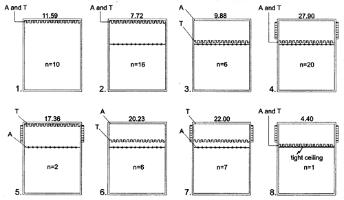
Figure 4 Ceiling Space Configurations. "A" and "T" are
the primary air and thermal boundaries, "N=xx" is
the sample size, and the number above each building is average ACH50
Leaky Ceilings Can Cause Leaky Buildings
Consider the building airtightness for the various configurations. In general, buildings with vented spaces above STB ceilings are leaky and those that are unvented are fairly tight. Configurations 4, 5, and 7 (vented) together have an average ACH50 of 25.7 ACH50. Configurations 1, 2, 3, and 6 (unvented) together have an average ACH50 of 11.1 ACH50. The buildings with vented ceiling spaces are 132% more leaky than those that are unvented. Therefore, we can say that if a small commercial building has a STB ceiling and the space above the ceiling is vented to outdoors, then the building will most likely be very leaky. It is also noteworthy that the single building which had a gypsum board ceiling had an airtightness of 4.4 ACH50, in line with the tightness of new residences which also have gypsum board ceilings.
Leaky Ceilings Can Increase Cooling Loads
Locating the insulation on STB ceiling can substantially increase the sensible cooling load. This is true for configuration 3 and to a lesser extent for configuration 6. For both of these configurations, the ceiling space is outside the thermal boundary but inside the air boundary (ceiling space is not vented); this causes its natural condition to be hot and dry. Several factors work together to increase the sensible cooling load. First, location of the insulation at the ceiling instead of the roof deck causes substantially greater conduction to the ductwork because the ductwork is commonly located in this hot ceiling space. Air handlers may also be located in this space. For configuration 6, the ductwork is commonly above the insulation, but may in some cases be below the insulation, or partially above and partially below. While the ceiling space of configuration 2 may be 85F (29.4C) on a summer afternoon, the ceiling space of configurations 3 and 6 may be 115F (46.1C). Conduction from the 115F (46.1C) ceiling space air to the 60F ductwork air is more than twice as great compared to an 85F (29.4C) ceiling space. Second, conduction through the ceiling/roof assembly is greatly increased. This occurs because the insulation system on the ceiling has a greatly reduced R-value, as previously discussed. Third, the heat in the ceiling space can find its way into the occupied space by air transport. Various driving forces - including duct leakage, unbalanced return air, and unbalanced exhaust air - can transport the hot air from the ceiling space to the occupied space. Because the ceiling spaces for configurations 3 and 6 are not vented to outdoors, latent cooling load associated with uncontrolled air flows are typically small.
Leaky ceilings can substantially increase both the sensible and latent cooling load. This is true for configurations 4 and 7 which have ceiling spaces that are hot and humid. Conductive sensible heat gain to the space occurs in the same manner and to approximately the same extent as was described for configurations 3 and 6 in the preceding section. However, because the ceiling space or attic space air is also humid, there is a latent load element as well, which occurs primarily as a result of air transport. In fact, the latent impact of infiltration air is typically greater than the sensible impact during hot and humid weather conditions. If indoor conditions are 76F (24.4C) drybulb and 56F (13.3C) dewpoint temperature and ceiling space conditions are 115F (46.1C) drybulb and 80F (26.7C) dewpoint temperature, then the latent load of the air transported from the ceiling space is 1.55 times that of the sensible load.
Uncontrolled Air Flow and Leaky Ceilings
Air flow occurs when there is a hole and a driving force. Since STB ceilings are leaky, they can be thought of as a visual barrier with a large hole in it. Four types of uncontrolled air flow have been identified; 1) naturally driven air flows, 2) duct leakage, 3) restricted return air, and 4) unbalanced exhaust air (Cummings et al, 1996). Naturally driven air flows occur because of wind and temperature induced stack effect. However, mechanically induced uncontrolled air flows typically have greater impacts on cooling load.
Return leaks can draw air from the hot (and perhaps humid) ceiling space. This can substantially increase cooling loads. Supply leaks can also move air from the ceiling space to the occupied space, by depressurizing the occupied space and/or pressurizing the ceiling space (if the supply leakage is to the ceiling space). If the ceiling space is cool and dry, then this air flow will cause minimal energy impacts. If the space is hot, or both hot and humid, then the impacts upon both cooling energy use and indoor humidity may be large.
Unbalanced return air also moves air across the ceiling. This occurs when the return or returns are centrally located, but supply air is delivered to each individual room. In this configuration, the doorway to each room functions as part of the air distribution system. When the door is closed, return air is blocked, causing positive pressure in the closed rooms which pushes air from the rooms into the ceiling space. At the same time, the central zone is depressurized by the return(s), and this depressurization draws air from the ceiling space into the occupied zone.
Unbalanced exhaust air often moves air from the ceiling space to the occupied space because the exhaust system depressurizes the building. This occurs because the incoming air flows (make-up air and outdoor air) are less than the exhaust flow. For each of these uncontrolled air flows, the issue is the same - that the energy and humidity impacts of air flow across the ceiling are greatly reduced if the ceiling space is inside the air and thermal boundary of the building.
Summarizing the conclusions of current practice:
- STB ceilings are leaky; that is they represent a large hole in the building.
- the building envelope tightness depends upon whether the space above the ceiling is vented to outdoors. If not, the building may be quite airtight.
- the thermal and humidity conditions in the ceiling space are a function of the location of the thermal barrier, whether the ceiling space is vented, and the degree of uncontrolled air flow across the ceiling plane.
- ceiling space conditions and the presence or absence of uncontrolled air flows determine whether a leaky ceiling impacts space conditioning energy use, the building ventilation rate, or indoor humidity.
Best Practice: Locate the Air and Thermal Boundaries at the Roof Deck
What does this mean? First, it means that the space above the ceiling is not vented, it is tight to outdoors. Second, it means that the insulation is at the roof deck. As a consequence, the space above the ceiling will be at least quasi-conditioned, since it is inside both the air and thermal boundaries of the building, and the conditions in this space will be typically more like the occupied space than outdoors. Referring to Figure 4, best practice would be either configuration 1 or configuration 2.
Several factors influence the conditions which will occur in this best practice ceiling space; 1) the presence of ductwork in the ceiling space, 2) uncontrolled air flow, and 3) whether the building operates at positive or negative pressure.
- Ductwork in the ceiling space will provide a small measure of conditioning based on conductive heat transfer from the air inside the ducts to the ceiling space air.
- Various forms of uncontrolled air flow, if they exist in the building, will move air across the STB ceiling and may provide a large measure of conditioning of the ceiling space.
- If the building operates with positive pressure (incoming air flows are greater than exhaust air flows), then conditioned air will move from the occupied space into the ceiling space and the space above the ceiling will tend to be cool and dry during the summer and reasonably warm during the winter. If the building is depressurized, then outdoor air will be drawn into the ceiling space. If a large portion of the building leakiness is between the ceiling space and outdoors, then the ceiling space will tend to become warm and humid (except dry climates) in the summer and cool and dry in the winter.
The fact that the ceiling space is quasi-conditioned has substantial implications for energy use, indoor relative humidity, and the building ventilation rate (the following discussion is made from the point of view of hot and humid summer weather).
First, ductwork and air handlers located in this space will be bathed in a more benign environment, and therefore conductive heat gains to the ductwork will be greatly reduced. For example, if the air in the ductwork is at an average 60F (15.6C) and the ceiling space is at 85F (29.4C), then the conductive load will be less than half compared to a ceiling space that is at 115F (46.1C).
Second, the impacts of return duct leakage may be greatly reduced. Return duct leaks often draw air from the ceiling space, and if the temperature is 85F (29.4C) compared to 115F (46.1C), then the sensible load impacts of this leakage is about four times less (assume room air of 75F (23.9C)). Also important, the dryness of the ceiling space air will mean greatly reduced latent load impacts when return leaks exist. Note that ceiling space or attic space dewpoint temperatures are often higher than outdoors during the hot hours of the day when the return leakage will most operating. The authors have found attic dewpoint temperatures as high as 95F (35.0C) during the heat of the day, some 20F (11.1C) higher than outdoor dewpoint temperatures (Cummings, Withers, and Moyer, 1999).
Third, conductive gains through the ceiling insulation system are greatly reduced. As noted earlier in this paper, the effective R-value of R19 h-ft2-F/Btu (3.34m2-K/W) batts located on a STB ceiling may be as low as R3 h-ft2-F/Btu (0.53m2-K/W) when insulation voids caused by drop-in light fixtures and out-of-place insulation batts are taken into account. By contrast, when the insulation system is located at the roof deck, then the thermal barrier is more nearly continuous and the effective R-value of R19 insulation materials is likely to be in the range of R14 to R19, depending upon the application (R14 if batts are located below roof deck between trusses or R19 if continuous insulation panels within the roof system).
Fourth, cooling loads associated with air flow across the ceiling are greatly reduced. Various forms of uncontrolled air flow (in addition to return leaks) can move air across the leaky ceiling plane, but if the conditions in the ceiling space are benign, then the impacts on energy use and relative humidity will be greatly diminished.
Best Practice Means a Tight Building
Locating the air barrier at the roof deck (i.e., this means not venting the ceiling space) will cause the building to be more airtight. A tight building has two major advantages. First, uncontrolled ventilation will be minimized. Second, the building can readily maintain positive pressure. To maintain positive pressure one needs greater incoming air flows than exhaust air flows, and a relatively tight building shell. It is important, especially in hot and humid climates, to maintain a building at positive pressure, because this positive pressure will push relatively dry indoor air outward. This will tend to keep exterior walls and other building cavities dry. By contrast, negative pressure will draw humid outdoor air into the building, and most specifically into wall cavities and other building cavities. As a consequence, the interior of exterior walls will experience high relative humidity or even condensation (depending upon the dewpoint of the air and the temperature of the wall surfaces). If this negative pressure persists for even a matter of weeks, there is considerable likelihood that mold and mildew growth may occur inside the walls.
Note that there are disadvantages which may result from tight construction. If the building is tight and no mechanical ventilation is provided, indoor air quality may suffer. If the building is tight and exhaust flows are greater than incoming air flows, then the building will experience significant depressurization, which can lead to problems with radon entry, sewer gas entry, and backdrafting and other problems related to combustion appliances. In some buildings, depressurization may become sufficiently extreme so that it is difficult to open exterior doors and combustion appliances may experience flame rollout. Therefore, buildings should not be over tightened. The tighter buildings become, the greater the potential for major failures. Consider an example of a restaurant which has exhaust air, make-up air, and outdoor air, and the building operates at a slight positive pressure. If the drive belt for the make-up air unit breaks or the motor burns out, then the building will suddenly be operating at substantial negative pressure. The tighter the building, the greater will be the unwanted depressurization. In one restaurant tested by the authors, switching off the make-up air unit took the building pressure from -0.112 inWC to -0.416 inWC (-28 pascals to -104 pascals). The building ACH50 was 3.9. Our recommendation is that building airtightness fall in the range of 4 to 8 ACH50. In our opinion, 4 ACH50 is sufficiently tight to adequately contain the conditioned indoor air and maintain a positive pressure field in the building, while generally avoiding the problems associated with a "too-tight" building.
Double Thermal Barrier
Locating the primary air and thermal barriers at the roof does not preclude also placing insulation on top of the ceiling. While this insulation may not greatly reduce heat transfer across the ceiling, it will provide some additional measure of occupant comfort and energy savings, and it will also reduce sound transmission from one zone to another. In this circumstance, because the primary thermal barrier is at the roof deck it does not become a critical problem if insulation batts are flipped.
Conclusions
Small commercial buildings in central Florida are considerably more leaky than single family residences. The primary factor is suspended t-bar ceilings. Due to the nature of its construction, the suspended t-bar ceiling is very leaky. The presence of a suspended t-bar ceiling, however, is not enough to cause a building to be leaky; the necessary second variable is that the ceiling space must be vented or leaky to outdoors.
Additionally, leaky ceilings contribute to unwanted air flows. Various types of uncontrolled air flow - including duct leaks, unbalanced return air, and unbalanced exhaust air - can drive air flow across the ceiling. The impacts of these uncontrolled air flows depend upon the thermal and humidity conditions which exist in the ceiling space.
- If the ceiling space is not vented and the insulation is located at the roof deck, then the ceiling space will be cool and dry (summer) and the consequences of uncontrolled air flow in terms of energy, humidity, and ventilation rates will be minimal.
- If the ceiling space is not vented but the insulation is at the ceiling, the ceiling space will be hot and dry (summer) and as a consequence cooling energy use will increase, indoor humidity will likely decrease, and ventilation will remain largely unchanged.
- If the ceiling space is vented and the insulation is at the ceiling, then the ceiling space will be hot and humid and uncontrolled air flow will cause significant or even major increases in cooling energy use, indoor relative humidity, and building ventilation.
Best practice: locate the insulation at the roof deck and do not vent the ceiling space. In this configuration, the ceiling space will be cool and dry (summer), R19 h-ft2-F/Btu (3.34m2-K/W) insulation materials will yield an effective R-value of R14 h-ft2-F/Btu (2.46m2-K/W) to R19 h-ft2-F/Btu (3.34m2-K/W) instead of R3 h-ft2-F/Btu (0.53m2-K/W) when insulation is located at the ceiling. Using the best practice approach, ductwork located in the ceiling space will not experience significant conductive heat gains or losses, and uncontrolled air flow across the leaky ceiling will produce only small impacts on cooling energy use, indoor humidity, and building ventilation rates.
Acknowledgements
Funding for the research on 69 small commercial buildings was provided by the Florida Energy Office of the Florida Department of Community Affairs.
References:
Cummings, J.B., C.R. Withers, N. Moyer, P. Fairey, and B. McKendry. 1996. "Uncontrolled Air Flow in Non-Residential Buildings; Final Report" FSEC-CR-878-96 Florida Solar Energy Center, Cocoa, FL, April, 1996.
Cummings, James B., Charles R. Withers, and Neil Moyer, "Field Research to Verify Duct Air Leakage Measurements and Distribution Efficiency Computations of ASHRAE Standard 152P", Florida Solar Energy Center, July 1999.
© 2007-2014 University of Central Florida. The Florida Solar Energy Center (FSEC)
is a research institute of the
University of Central Florida.
For more information about FSEC, please contact us or learn more about us.
Find us on Facebook!