

Reference Publication: Parker, D., Callahan, M., Sonne, J., Su, G., "Development of a High Efficiency Ceiling Fan, 'The Gossamer Wind'," Florida Energy Office, Department of Community Affairs, Tallahassee, FL. Disclaimer: The views and opinions expressed in this article are solely those of the authors and are not intended to represent the views and opinions of the Florida Solar Energy Center. |
Development
of a High Efficiency Ceiling Fan
"The Gossamer Wind"
Danny
S. Parker, Michael P. Callahan, Jeffrey K. Sonne ,
Guan H. Su
Florida
Solar Energy Center (FSEC) and AeroVironment,
Inc.
FSEC-CR-1059-99
Introduction
Design Objectives
Particulars
Test Bench
Testing
Comparative Performance
Automated Ceiling Fan Controls
Control Logic
Energy Efficient Light Kit
Noise
Advantages of the Gossamer Fan in Application
Fan motors
Future Work
References
The potential of ceiling fans to improve comfort during the cooling season is well documented (Rohles et al., 1983; Fairey et al., 1986). There are at least two cases: In the first where air conditioning is unavailable, adding ceiling fans may significantly improve building comfort and health although actually increasing energy use. However, the more common circumstance is where ceiling fans are used with the objective of providing a higher cooling system thermostat set point with acceptable comfort. Fans can also potentially avoid the use of air conditioning during "swing" seasons. Although studies commonly suggest a 2 - 6oF increase in the thermostat set point, data from 386 surveyed Central Florida households suggests that although fans are used an average of 13.4 hours per day, no statistically valid difference can be observed in thermostat settings between households using fans and those without them (James et al., 1996). Part of this may be due to the lack of sufficiently wide air distribution coverage within rooms (Rohles et al, 1983; Sonne and Parker, 1998).
Studies touting potential cooling savings of up to 40% have usually been sponsored by fan manufacturers (eg. A.D. Little, 1981). These often make unrealistic assumptions such as presuming that occupants are within four feet of a fan at all times with only one fan is in use, and a 6oF elevation of the thermostat setting. An environmental chamber study by Consumer Reports showed that the long-reported de-stratification benefits when heating are largely unsubstantiated (Consumer Reports, 1993). Thus, benefits from ceiling fans can only reduce cooling needs and this is completely contingent of sufficient changes in interior comfort to warrant raising of the cooling thermostat.
Two other factors must be taken into account in assessing the benefits of fans: their actual energy use and the added internal heat gains produced by the fans during operation. The measured electrical demand of ceiling fans varies between 5 and 115 Watts depending on model and speed selection. A power demand of 40 W at medium speed is probably typical (Chandra, 1985). Thus, a fan used for six months of the year would use 175 kWh. With 4.3 ceiling fans in an average Florida home, this amounts to about 800 kWh of fan energy consumption-- about 5% of total electricity use. Also, all of the energy use of fan is eventually converted to heat within the home which must eventually be removed by ventilation air or the cooling system.
Design Objectives
In the fall of 1996, the Florida Solar Energy Center (FSEC) set out to create an improved ceiling fan design which would provide better air moving efficiency while reducing energy consumption. The project was described on December 10, 1996 with goals of improving three areas of current ceiling fan design: the ceiling fan blades, controls, and motor. Our design objectives for the improved ceiling fan blade design were as follows:
-
Maximum air flow (cfm) per input watt [typical designs produce 150-200 cfm/W]
-
Air flow distribution (uniform air movement throughout the room)
-
Quietness of operation
Particulars
-
1 Fan blade span diameter: 1.32 m (52 inches)2 Operational speed: 50-150 rpm [typical fans operate at 50 - 200 rpm]
-
3 Geometry of adjacent surfaces: top surface (ceiling) 0.31m (12 inches). Lower surface (floor) at a distance of 2.29m (7.5 feet) and 2.14m (7 feet). Four walls surfaces 2.75m (9 feet) equidistant from the fan.
In lieu of a more efficient motor (which is still an objective for
the project) our goal was to see if a smaller, less expensive motor
could be used with superior fan propeller blades to create performance
equivalent to the best ceiling fans using larger motors, providing both
improved energy efficiency, potentially lower cost, and superior comfort.
The final design is shown in Figure 1.
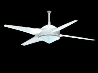
Figure 1. Computerized rendering of the "Gossamer
Wind" ceiling fan.
Blades are true air foils with both taper and twist.
Development
The Florida Solar Energy Center (FSEC) provided the initial criteria
to AeroVironment of Monrovia, California on December 23, 1996.
In January 1997 we worked together to come up with a ceiling fan propeller
design which would improve energy efficiency and comfort effectiveness.
On February 14, 1997 AeroVironment provided data from numerical
simulations suggesting three potential ceiling fan designs.
The design objective was a fan producing air flows of 2 meters/second
across the blade radius at a speed of 150 - 200 rpm. FSEC evaluated
the three designs and selected the tapered design which suggested the
best performance. AeroVironment made refinements in the design
in March of 1997, providing cross sections for design Ceiling Fan-1
(CF-1) which was later renamed the Gossamer Wind. The design featured
tapered, twisted blades with a true air foil. The simulated cross
sections are shown in Figure 2.
Figure 2. Computer generated air foil sections showing how
fan
blade twist increases as ceiling fan root is approached.
Bart Hibbs, the prime engineer performing the numerical simulations, estimated that the Gossamer Wind fan would provide roughly twice the air moving efficiency that would be obtained with conventional flat untwisted blades. It was estimated that about 8 watts of shaft power would be required to meet rated performance.
Throughout the spring of 1997 we worked at fabricating the ceiling fan blades. Two approaches were made to produce the blades. One method, to create a wood mold on which fiberglass shells would be cast was attempted, but failed. We eventually decided to create each prototype blade by using a cross section of the blade airfoil at each of the measurement stations mounted onto a metal crossbar running the length of the blade (Figure 3). Struts were then glued between the ribs to provide racking strength with thin balsa wood sheets applied to the ribs as a cover (Figure 4). These were then glued in place and sanded smooth. Four blades were eventually produced with very close tolerance to the original design. Figure 5 shows the completed balsa wood prototype. The process was labor intensive, however B over 140 hours were required to fabricate the blades.
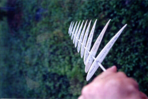
Figure 3. Airfoil templates of varying chord lengths
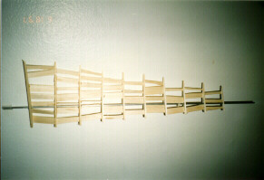
Figure 4. Balsa spars were created to strengthen the blades
along the chord length
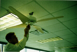
Figure 5. Jeff Sonne mounts his completed prototype blades
onto motor test assembly.
The blades were then mounted on adjustable brackets so that the pitch of the blades could be altered during test. The balsa blades are approximately 6.5" wide at the blade root tapering to just 2.5" at the rounded tip. The blades are approximately 20.5" long with an estimated surface area of 93 square inches. Unlike the flat bladed ceiling fans, the propellers for the design are highly twisted. Under the design specification, the pitch with respect to the plane of rotation varies from 26.5 degrees at the blade root to 6.9 degrees at the rounded blade tip. The airfoil shape is based on a low velocity design (GM15) derived from wind tunnel testing performed at the University of Illinois. Each prototype blade weighs 175 grams with mounting hardware. The overall blade diameter with mounting hardware is 52 inches B identical to a standard ceiling fan size.
Test Bench
In May of 1997 a test laboratory was set up at FSEC (Figure 6). The test bench consisted of three major elements. First was a digital hot wire anemometer (Solomat MP 5000) which was mounted on a tripod at a 56 inch height with an accuracy of 0.05% of full scale reading. The second was a precision digital watt hour meter (Valhalla 2100) with a resolution of 0.1 W. A hand-held Solomat infrared tachometer was used to measure ceiling fan speed (rpm) shown in Figure 7. The ceiling fan was located in a large open room with nine foot ceilings (106.5"). The ceiling fan mounting bracket was located on the ceiling at the south section of a room. The distance to each adjacent wall was as follows:
Center to West: 8.8 ft
Center to East: 10.8 ft
Center to South: 5.9 ft
Center to North 43.8 f
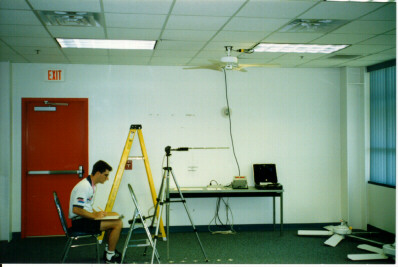
Figure 6. Research assistant, Mike Callahan, measures
ceiling fan air velocity profile in test laboratory.
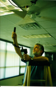
Figure 7. Danny Parker checks fan rpm at high speed.
During the early summer 1997, three conventional ceiling fans were acquired for comparative testing. These included two Emerson models and one Hunter ceiling fan. These two manufacturers were selected since Emerson leads the industry in the production of ceiling fan motors and Hunter claims some of the highest quality fans. The Hunter fan ("Summer Breeze") was recently rated as one of the best ceiling fans in terms of air moving efficiency in a recent issue of Consumer Reports. The two Emerson fans consisted of a low cost model ("Northwind" CF705) and a more expensive 5-bladed fan ("Premium" CF4852) which represented a part of the upper end market designed to move more air (larger K55 motor). The low cost fan, with a cost of $70, represented a very large part of the current ceiling fan market. It consisted of a fan with four flat blades and an inexpensive 50 watt shaded pole induction motor. The motor was manufactured for Emerson in Singapore. The flat blades had a nominal tilt of 12.5 degrees although we measured only an 8 degree pitch on our test bench when assembled. The flat ceiling fan blades were identical for both ceiling fans and represented the standard design within the industry. They consisted of rounded rectangular blades with a width of 5" at the blade root up to 5.5" at the tip and were 20 inches long. The estimated blade area was approximately 103 square inches. They were made of painted wood and each had a measured weight of 329 grams with mounting hardware.
The fans were mounted using existing hardware as they came out of the box. Each tested fan came with only a 3" down rod which connected the fan motor to the mounting bracket. This resulted in the fans being installed so that the ceiling to blade tip distance was about 9.25". The air flow measurements were made underneath at a distance of 43" from the floor in accordance with ASHRAE Standard 55-1992.
Air flow measurement locations were established for the measurements by marking off 12 stations with the first immediately below the centerline of the fan and the others at six inch increments from the centerline (Figure 8). Since the fan blade and motor has a diameter of approximately 52", the first six stations comprised the locations which cover the blade sweep; the remaining six stations (3 - 6 ft from the fan centerline) represented the fan air entrainment zone.
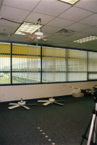
Figure 8. Air velocity test evaluates air moving efficiency
at 1/2 ft. increments from fan center
Testing
Testing was done by mounting each fan in turn and evaluating the three fundamental quantities:
-
Flow (m/s)
-
Power (W)
-
Speed (rpm)
The air flow measurements were taken at each of the air flow stations. Three repetitions were conducted for each air flow station. The fans were first tested with the existing down rods which had been provided. This resulted in the fan blades being about 10" from the ceiling above. The results are shown in the tabular data as well as in the figures below.
Figure 9 shows the measured air flow in meters/second for the four differing fans at low speed operation over the six foot region comprising the measurement area. The legend also provides performance data in terms of motor power consumption and fan rpm. The FSEC/AeroVironment fan shows clearly superior performance to the flat bladed fans. The Hunter fan provides the most competitive comparable performance. Note that the Emerson CF705 fan and the prototype fan are using the same motor with different blades. Thus, it is possible to see the impact of the improved blades alone by comparing these two performance curves.
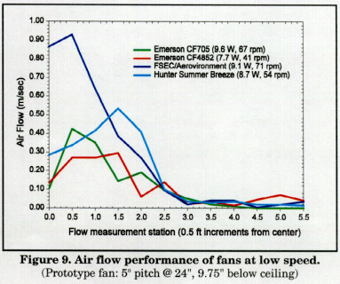
Figure 10 shows the measured performance of the four fans at high speed. Note that the power draws of the fans are quite different except for those of the prototype and the Emerson CF705 which use exactly the same motor. Only the Emerson CF4852 fan is able to match the air flow performance of the prototype fan and this comes only at considerable energy cost. The CF4852 with its larger K55 electric motor uses 93 Watts as opposed to the 50 watts used by the prototype B a reduction in relative energy use of 46% with similar air flow. The Hunter fan has the next best performance since its motors draws only 75 Watts at high flow. Interestingly, the data show that all the 52 inch fans only provided good air flow (>0.50 m/s) over the radius of the fan blades (2 feet B shown at measurement location five). All increases to measured air flow are essentially negligible by the time measurement station seven is reached (3 feet out from the fan). This argues for larger fan blades to increase fan coverage B a fact already described in a previous study assessing ceiling fan impact on comfort.
Figure 10. Air flow performance of fans at high
speed.
(Prototype fan: 5o @ 24", 9.75" below ceiling)
Comparative Performance
These data are graphically summarized in Figures 8 and 9. The measured air velocities (m/s) between each measurement station was then multiplied by the area of that specific area (m2) to yield a volumetric flow (m3/s). The flows for each fan were then summed over the relative areas between air flow stations extending out to three feet from the fan center where the flows of all fans dropped to background values (>0.1 m/s). The total flows were then converted into cfm for each fan. An efficiency index was produced by dividing the total cfm per fan by the measured motor wattage (cfm/W). Figure 11 shows Danny Parker (FSEC) and Guan Su (AeroVironment) reviewing test results. Table 1 provides the results for the low fan speed; Table 2 shows the same for the high speed setting.
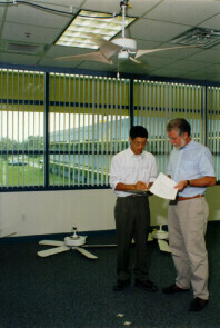
Figure 11. Fan developers, Guan Su, AeroVironment (left) and
Danny Parker, FSEC (right) discuss test data.
Table 1
Comparative Fan Performance and Efficiency at Low Speed
| Value
|
Emerson CF705 |
Emerson CF 4852 |
Hunter Summer Breeze |
FSEC/ Aerovironment CF-1 |
| CFM | ||||
| Watts | ||||
| CFM/W |
The CF705 and CF-1 fans use the identical motor, so the improvement in performance is solely a reflection of the change in the efficiency of the propeller blades. The air moving efficiency of the Emerson motor is increased by 86% B nearly doubling the overall performance. Both the Emerson CF 4852 and Hunter Summer Breeze use different motors, although motor draws are similar. The low speed performance of the Hunter fan is similar to the CF-1 prototype, mainly due to the fact that its air flow is highest towards the edge of the ceiling fan blade tips which encompasses a larger area.
Table 2 below shows the relative performance measured for each fan at high speed.
Table 2
Comparative Fan Performance and Efficiency at High Speed
| Value
|
Emerson |
Emerson |
Hunter |
FSEC/ |
| CFM | 3110 |
6057 |
5339 |
6471 |
| Watts | 50.2 |
93.1 |
74.8 |
49.6 |
| CFM/Watt | 61.9 |
65.1 |
71.4 |
130.5 |
At high speed the disparity between the prototype fan and that
of the other conventional models is even more pronounced. Keeping in
mind that the only difference between CF-1 and the Emerson CF 705 model
is the improved blades (they use the same motor), the prototype shows
a 111% increase in air moving efficiency. Not only does the CF-1 model
have the greatest air moving efficiency, but it also has the greatest
absolute flow B even more than the Emerson model using a motor
which draws 88% more power.
Automated
Ceiling Fan Controls
Conventional fans use pull chains or rotary wall switches which are often unintentionally left on even when no one is home. For instance, a survey of home owners by the Florida Power and Light Company, found that the average ceiling fan is on 13.4 hours per day with nearly a third of fans left on constantly year round (James et al., 1996; Sonne and Parker, 1998). This wastes electricity, since a ceiling fan can only improve comfort if someone is there to feel its air motion.
Smart controls for the "Gossamer Wind" were designed to greatly increase its convenience, energy savings and comfort potential. A 360-degree infrared motion sensor control automatically activates the fan when anyone enters a room and always remembers to turn it off when occupants are gone. Another control circuit, under development, adjusts the speed of the ceiling fan in response to room temperature conditions. A switchable photo optical sensor will be used in the production unit so that the fan will not be turned off by a lack of motion in darkness. This will prevent the control from turning off the fan in bedrooms while occupants are sleeping.
The automatic control system for the fan has been developed by FSEC in conjunction with the Wattstopper Corporation. Photographs of the prototype controller based CI-200 unit, is illustrated in Figures 12 and 13.
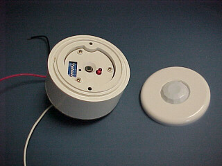
Figure 12. Control sensor showing internal switch settings
(sensitivity, light and time delay).
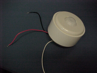
Figure 13. Prototype control unit appearance with 360o Fresnel
lens.
Control Logic
Operation of the control mechanism on the operation of the ceiling fan is described in the flow chart shown in Figure 14. The control system sequence begins to operate when electrical power is applied to the device. Once activated, the passive infrared (PIR) sensing mechanism scans through a 360 degree compound Fresnel lens. If it senses movement within its field of view at state, it checks to see if manual override has been set or the control does not sense thermal conditions. If the PIR sensors does not detect movement, it checks to see if the set time delay is expired. If the time delay has expired, it switches off the fan motor.
Figure 14. Automated control logic flow chart.
If, the time delay has not expired, it checks to see if manual override has been set or the control unit does not include temperature based speed control. If the override is specified or the unit is an occupancy sensing only model, it maintains the current ceiling fan speed at state.
If manual override is not set (or the control unit does not include temperature based speed control), the control checks to see if the room temperature is below the minimum setting. If it is, it deactivates the fan motor. Otherwise, if the control checks to see if the temperature is greater than the low setting and less than the mid-point between the high and low setting at state. If this is true it sets the fan speed to low speed. If the temperature is equal to or greater than the mid point of the set range, the control determined whether the temperature is less than the high temperature set. If it is not, it sets the fan speed to medium. If the temperature is greater than the high speed value, the fan is set to high speed at state. The entire sequence of readings and actions are then repeated as long as the fan control is powered.
Conventional fan light kits use a 100 W linear halogen lamp three or more 40 W incandescent bulbs. These which are often hard to reach, use considerable electricity when operating and require frequent replacement. The prototype AGossamer Wind@ has an energy-efficient light kit which fits within an attractive housing and provide up to 12,000 hours of superior lighting without a lamp change (Figures 15 and 16). Further, its energy savings will typically amount to more than $100 over the life of the fan.
Figure 15. Appearance of prototype fan with light kit.

Figure 16. Illumination of 20 W prototype light kit in a darkened
room
Most modern ceiling fans use a J-type halogen 100 W light kit (R7S halogen lamp: 1400 lumens, 2900K color temperature). The lamp's power consumption more than doubles the fan energy use when the lamp is energized: a ceiling fan motor typically only draws about 50 - 90 W at high power!
To address this problem, we adapted a 20 W circline lamp (Lights of America: 2620C-MPF) to fit within the standard lens of the light kit housing. The lamp puts out a pleasing warm light, which provides about the same lumens as the halogen (1450 lumens), although with a somewhat softer illumination. Unlike magnetic ballasted fluorescent lamps, the electric ballast in the 2620C provides instant-on capability.
Even more important though is the life expectancy: the compact fluorescent lamp (CFL) 2620C has a MTBF of 12,000 hours versus 2,000 hours for the 100 W halogen lamp. Thus, the CFL lamp will likely not need changing over the life of the fan. If the lamp kit was used for 3 1/2 hours per day, the new light kit would save 1,022 kWh over a ten year period compared with the standard configuration B equal to a money savings for energy savings alone of $82 at typical electricity prices.
Further, six R7S lamps would have to be replaced over the same time period; the current price at Home Depot for these lamps is $5.75 each: a total added cost of $34.50, not to mention the aggravation of going out to buy and installing the replacement lamps.
The retail price of the CFL lamp we used is $15 B cost to manufacture in production would certainly be less. The bottom line is that the new light kit alone in the new Gossamer prototype can save consumers at least $100 over the life of the fan. The more efficient fan will provide every greater savings as well as improved comfort.
Noise
Another question to be addressed was the noise levels of the different fan blade types. This was tested using a decibel meter. The background noise was measured first, then the fan motors in the Table 3.
Table 3
Sound Pressure (decibel) Levels at High Speed
Noise Level |
10 mm motor |
"Summer Breeze" |
"Landmark" |
| Test #1 57 db | |||
| Test #2 57 db | |||
| Test #3 57 db | |||
| Average 57.0 | |||
| Decibel over background |
Clearly, the Gossamer is the most quiet. The differences are larger than they appear since the decibel scale is logarithmic B sounds 10 dB louder have 100 times more sound pressure. It is expected that the quieter blade design will be more aesthetically appealing to the consumers.
Advantages of the Gossamer Fan in Application
-
Fan blades can be made part of the standard equipment with a smaller less expensive motor and still provide superior air flow to that achieved with larger more expensive motor and flat blades.
- Controls provide savings from reducing fan on-time when rooms are unoccupied, as well as providing improved convenience.
- The resulting combination of an existing motor with the FSEC/AeroVironment blades is more energy-efficient. This saves ~$10 - $20 per year in operation. First cost of the improved ceiling fan may be reduced by $50 - $100 over a fan providing similar performance using the K55 motor with flat blades.
- Energy efficient light kit can reduce associated energy use by 80% saving approximately $10 per year and reducing frequency with which bulbs must be changed.
- Improved aerodynamics of tapered blades are more quiet in operation than flat blades.
- Because of the even loading across the blade radius, the FSEC/AeroVironment prototype is less prone to wobble.
- If mated with a larger fan motor, a larger version of the current fan blades (e.g. 64" or 72" rather than 52" diameter) can potentially provide superior air flow to any ceiling fans with flat untwisted blades.
The shaded pole motors used by conventional ceiling fans are very inefficient. This is both due to limitations in the impedance protected shaded pole design as well as the low rpm rates at which ceiling fans operates. Tests on a small dynamometer of a conventional ceiling fan motor at Oregon State University showed a useful motor shaft output of only 12.8% at high speed (64.9 W) and only 2.6% at low speed (11.1 Watts).
All of the motor inefficiency is converted to heat. Heat produced by ceiling fan motors increases air conditioning cooling loads. The infrared thermograph in figure 17 shows color proportional to temperature. Waste heat produced by the motor as well as the very low efficiencies achieved, underscores the need for smaller, more efficient motors.
Figure 17. Infrared thermograph of a ceiling fan showing heat
produced by the motor.
Future Work
Currently, a light-weight and highly durable prototype blade is being tested that consists of a foam core material. Once this is fully developed, it will be tested to determine which size motor is best for both the 52" and 64" new prototypes. This will directly lead to a pre-production prototype version which will precede large-scale manufacturing.
Since it has been determined that the new blade design was superior to standard flat blades, a larger version is also being constructed to provide better room airflow distribution. The larger design (Figure 18) has a 64" diameter and was constructed of plastic using stereo lithography. The results of initial tests will be posted in the near future.
Figure 18. The 64" Gossamer Wind prototype
ASHRAE. 1992. ASHRAE Standard 55-1992: Thermal Environmental Conditions
for Human Occupancy, Atlanta, Georgia: American Society of Heating,
Refrigeration and Air-Conditioning Engineers, Inc.
Chandra, S., 1985. "Fans to Reduce Cooling Costs in the Southeast," FSEC-EN-13-85,
Florida Solar Energy Center, Cape Canaveral, FL.
Consumer Reports, 1993. "Ceiling Fans," Consumer Reports,
June, 1993.
Fairey, P., Chandra, S. and Kerestecioglu, A., 1986, Ventilative Cooling in Southern Residences: A Parametric Analysis, FSEC-PF-108-96, Florida Solar Energy Center, Cape Canaveral, FL.
James, P., J. Sonne, R. Vieira, D. Parker, and M. Anello. 1996. "Are Energy Savings Due to Ceiling Fans Just Hot Air?" Proceedings of the ACEEE Summer Study on Energy Efficiency in Buildings, 8:89-93, American Council for an Energy-Efficient Economy, Washington D.C.
Little, A.D., 1981. Energy Savings Resulting from the Use of a Hunter Ceiling Fan, Phase II Final Report, prepared for Ribbins and Meyers, Inc., Cambridge, MA.
Parker, D.S., et al, 1998. "High Efficiency Ceiling Fan," Patent Application, Docket No. UCF-185.
Parker, D.S., et al, 1998. "Automatic Occupancy and Temperature
Control for Ceiling Fan Operation," Continuation-In-Part of Parent
Application: UCF-185, Title: High Efficiency Ceiling Fan, Docket No.
UCF-191CIP.
Rohles, F.H., S.A. Konz and B.W. Jones, 1983. "Ceiling Fan as Extenders
of the Summer Comfort Envelope," ASHRAE Transactions, Vol.
89, Pt. 1A., American Society of Heating, Refrigeration and Air Conditioning
Engineers, Atlanta, GA.,p. 51.
Sonne, J.K. and Parker, D.S., 1998. "Measured Ceiling Fan Performance and Usage Patterns: Implications for Efficiency and Comfort Improvements," Proceedings of the ACEEE Summer Study on Energy Efficiency in Buildings, Vol. 1, p. 335, American Council for an Energy-Efficient Economy, Washington D.C.
"Stirring up a Breeze: Ceiling Fans Test," Consumer Reports, Vol. 62, No. 7, July, 1997. P. 44-47.
Wallace, Alan. 1998. "Progress on Fan Motors" memorandum
to D. Parker, Dept. of Electrical Engineering, Oregon State University,
Feb. 23 and April 9, 1998.
* Submitted to:
Florida Energy Office
Department of Community Affairs
2555 Shumard Oaks Blvd.
Tallahassee, FL 32399
© 2007-2014 University of Central Florida. The Florida Solar Energy Center (FSEC)
is a research institute of the
University of Central Florida.
For more information about FSEC, please contact us or learn more about us.
Find us on Facebook!