

Field
Evaluation of Efficient Building Technology
with Photovoltaic Danny S. Parker,
James P. Dunlop, John R. Sherwin,
Stephen F. Barkaszi,
Jr.,
FSEC-CR-1044-98
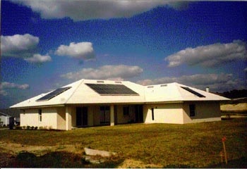
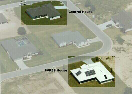
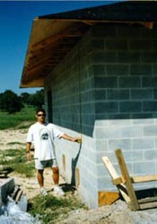
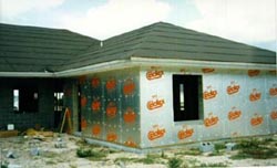
Table of Contents The objective of the project, sponsored by the Florida Energy Office and Sandia National Laboratories, is to test the feasibility of building very efficient residential buildings that when combined with utility-interactive PV power, exert little net demand on the utility during the summer peak demand period. Two single family homes - one, a super efficient residence with a utility interactive photovoltaic (PV) system, and another, a control home - have been constructed in Lakeland, Florida. The PV residence, or PVRES, was constructed with many measures designed to make it more efficient (Fig. E-1). These include a white tile reflective roof system, solar control windows with wide overhangs, an interior duct system, a high efficiency air conditioning system, efficient lighting, and propane used for major appliances which commonly use resistance electricity (range, dryer and heat). A solar water heater with propane back up provides domestic hot water. For comparison, a building with an identical floor plan, but without the efficiency features, has been constructed to test the concept. A 4 kW PV system was mounted on the roof of the PVRES building in a split array arrangement with 2.7 kW facing south and 1.3 kW facing west. The west facing array was included in the project to augment solar power production during the late afternoon peak demand period. Exterior wall insulation is used over the concrete block construction to encapsulate the building thermal mass. This construction, along with a programmable thermostat, is used to shift the building cooling load earlier during the day when the PV power production is greatest. A data acquisition system was installed at each site for comparative monitoring of relative energy consumption and, for the PVRES, PV power production. The local municipal utility, Lakeland Electric & Water, owns and operates the PV system. Figure E-2 shows the measured cooling load profile on a hot day (May 17, 1998) with similar interior conditions maintained and both homes unoccupied. The Control home's air conditioning load averaged 3.62 kW during the peak hour between 5 and 6 PM EDT while the PV home had a cooling demand during the same hour of 0.50 kW - a reduction to the utility coincident peak load of 86%. Over the same period, the average PV power production averaged 619 Watts, thus sending valuable electricity to the grid when most needed by the utility. Total daily electricity consumption for cooling was 5.84 kWh in the PV home against 37.5 kWh in the Control home - a reduction in daily cooling energy of 84%. Moreover, the PV system produced 17.9 kWh - three times as much electricity on this day as the cooling system used.
Based on comparative summer monitoring, energy efficient housing incorporating PV not only can reduce total electrical consumption by more than 70% over traditional housing, but also can be a viable means to eliminate the peak load posed by the cooling system on the utility during its coincident peak demand period. In early June, 1998, the PVRES home was occupied with the load shift temperature control instituted, while the unoccupied Control home continued to maintain a constant thermostat setting, but with no appliance or lighting energy use. Lakeland Electric & Water experienced their annual summer peak power demand at 5 PM on June 18th, 1998 - a day with the hottest daytime temperatures on record for Lakeland, FL. On June 18th, the occupied PVRES home showed dramatically lower cooling and total electricity requirements than the unoccupied control house. Over the 24 hour period, the PVRES home only used 28% of the air conditioning power that the Control home required. During the utility peak period the Control home air conditioner required 2,980 Watts (average) as opposed to 833 W for the PV home - a 72% reduction. When the PV electric generation is included during the same peak period, the PVRES home net demand was only 199 W - a 93% reduction in electricity requirements from the 4.5 kW required for the Control home. As shown in Figure E-3, the PVRES home showed little net demand on the utility during daytime hours. Over the month of June, the PV system produced 60% of the power required for all electrical end-uses by the PVRES house (837 kWh). Against this, the Control home used 1,739 kWh in June solely for air conditioning. about 5,600 kWh.
In summary, the Lakeland project has conclusively shown
that it is possible to construct homes in Central Florida
which use only a fraction of the air conditioning and other
appliance electricity consumption of standard construction.
When coupled with PV electric generation, such efficient
construction practices demonstrate the feasibility of building
homes which exert little net impact on the utility grid
during peak summer periods. During non-peak periods such
homes could provide clean, renewable electricity to the
utility and its customers. This report summarizes the first summer performance of
a project design to test the feasibility of designing and
testing very efficient new residential buildings with integrated
photovoltaic (PV) generation systems to meet cooling system
and other electrical loads in a hot humid climate. The demand for electrical energy in Florida is increasing continually as a quarter of a million people move to the state each year building over 100,000 new homes [1]. To meet this demand, utilities must add new generation facilities and associated infrastructure. Most Florida utilities are interested in seeing how load growth during the summer peak demand hours can be effectively controlled. This project is investigating how to reduce residential electrical demand by incorporating energy efficiency and photovoltaic arrays into new residential construction. A typical new three bedroom single family residential home in the Central Florida area consumes about 15,000 kWh annually with diversified peak demands in the late summer afternoon of approximately 4.0 kW per residence between 4 and 6 PM [2]. Larger new single family homes may use even more electricity. A 2,425 square foot test home was built in Lakeland which
incorporates many measures designed to make it more efficient.
This includes a reflective roof system, advanced windows,
an interior duct system, wider overhangs, more efficient
lighting, a high efficiency air conditioning system and
propane used for major appliances which commonly use resistance
electricity (range, dryer and heat). For comparison, a
control house with an identical floor plan, but without
the efficiency features, has been constructed to perform
a real-world test of the concept potential. The central objective of the project is to test the feasibility of constructing new single family residences which are engineered to reduce air conditioning loads to an absolute minimum so most of the cooling and other daytime electrical needs can be accomplished by the PV component. The project objectives were:
Design and Simulation Analysis Previous work sponsored by the Florida Energy Office has simulated the possibility of greatly reducing the cooling loads in a conventional new home and then supplying most the cooling and other electrical needs with a grid-connected 3 - 4 kW PV array [3]. The results showed that the cooling system of such of a home might be reduced to as low as to be served by an air conditioner with a capacity as little as a single ton (12,000 Btu) capacity. The home was to feature a group of efficiency measures and high efficiency cooling equipment and appliances. PVRES Home Features The PV-integrated (PVRES) home would have a number of integral elements designed to minimize cooling loads as described in the initial concept. The specific individual measures have been simulated in detail and measured in several field projects [4-9].
Control Home Features The basic features of the Control home to be constructed are indicative of current residential building practice in Central Florida.
After choosing the specific measures, we simulated the two buildings using a special version of the DOE-2.1E hourly building energy simulation. The version, EnergyGauge USA, includes the capability to examine interactions between the duct system location and the space cooling efficiency. This is important since both heat transfer to and leakage of the duct system can substantially influence cooling efficiency [10, 11]. Two building simulation decks were created, one designed
to approximate the Control home and the other to represent
the PVRES design with its improvements. The simulation
predicted the annual energy use of the Control building
would be 22,740 kWh/year when occupied against 8,489 kWh
for the PVRES home. The predicted end uses are detailed
in the table below: Table 1
* Estimated annual propane energy use is 32 gallons for
back-up heat. Our initial analysis indicated a 66% reduction by the PVRES building for space cooling and a 63% overall reduction in electricity consumption in the occupied homes when operated in a similar fashion. We also ran the PVRES and control homes with Florida Energy Gauge Rating software. It predicated annual energy costs for the Control and PVRES homes of $1,459 and $814, respectively (a reduction of 44%). It also showed a 51% reduction in space cooling predicted consumption (5028 kWh vs. 2440 kWh). The predicted savings by the Florida Energy Gauge software was expected to be lower since it cannot currently simulate the cooling reduction impact of the white reflective roofing system. The electric load profile shape was predicted to differ in the two homes. An end-use in Central Florida is air conditioning. With exterior insulation over the masonry construction, the thermal capacitance of the PV home was slightly over-cooled during the daytime hours, rising during the late afternoon gaining greater utilization of the solar resource, and reducing loads during the utility peak period. Figure 1 illustrates the predicted performance on the utility peak day.
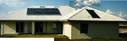
FSEC worked with a builder in the vicinity of Lakeland, Florida to construct the two homes. The location was important since the City of Lakeland and its municipal utility was willing to consider a grid-connected PV system. One of the houses was to be of standard construction with typical appliances, insulation and equipment. The experimental home would contain the efficiency improvements and the PV element. Both would be extensively monitored. In March 1997, FSEC met with builders in the Polk County area to solicit participation. Simultaneously, we met with Lakeland Electric & Water to settle on project objectives and monitoring data. A set of detailed building specifications for the project were then composed. We had interest from three builders relative to the project. Of these, one builder was not within the Lakeland Electric and Water service territory, and another was uncertain of when two homes of similar construction could be built. Consequently, we met with and chose Rick Strawbridge of Strawbridge Construction for the Project. The builder chose a 2,540 square foot one story floor plan which he had previously built. The elevations for the building plan (virtually identical in both the Control and PVRES home) is shown in Figure 2.
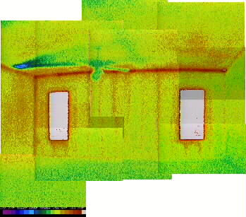
Essentially, the project began in the spring of 1997 with construction of both the Control and PVRES homes starting in August. The conventional control home was complete with instrumentation by March 1998. The PVRES home was complete with all equipment and instrumentation by April of 1998. Figure 3 shows the location of the two homes within the Windwood Hills development in Lakeland.
The specific efficiency features in the PVRES house are detailed below: Wider Overhang In Florida "Cracker" homes, built at the turn
of the century before air conditioning, wide porches and
deep overhangs were considered essential to achieve comfort
[12]. However, with the advent of air conditioning, many
new homes have sacrificed overhangs in interest of first
cost. New residences in modern developments often have
practically no overhangs.
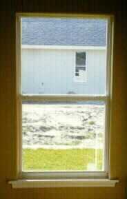
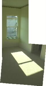
Exterior Wall Insulation In conventional residential construction in Florida, walls are insulated with R-3 to R-5 ft2 · h · oF/Btu insulation on the interior of the masonry walls. Although, this may seem low relative to building practices in northern climates, previous field monitoring has shown that a insulation can only reduce space cooling by 5-10% in Florida's climate [8]. The most common wall insulation system in Florida to meet the insulation requirement is a layer of foil (Fi-foil Reflective Insulation) suspended between interior furring strips with an equivalent insulation value of R-4.2. Figure 6 shows the interior east wall of the control home in the early afternoon. The effectiveness of the Fi-foil is seen with the fact that the furring strips are warmer than the low emissive surface in between.
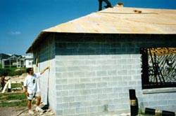
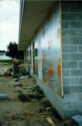
However, the concrete block walls of the PVRES home were better insulated on the exterior both in order to assist with reducing the cooling system size and to help with the load shift objective within the project. The Celotex Corporation supported the project by providing 1¼" Tuff-R C isocyanurate insulation and worked with the builder to resolve issues associated with the unusual application (Figure 7).
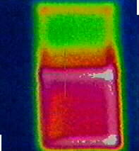
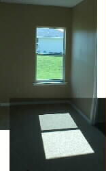
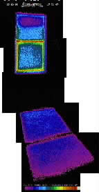
An exterior application was used to encapsulate the building in R-10 insulation so that the masonry portion of the building could be pre-cooled during the daytime hours when solar availability is high and the PV system output is at its maximum. The intent was to utilize the thermal capacitance of the building and its masonry to help to reduce air conditioning needs during the late afternoon and early evening hours. Advanced Solar Control Windows Windows are known to be the large source of cooling loads in Florida residential buildings.[13] Generally, a low Solar Heat Gain Coefficient (SHGC) is needed to keep out the sun's heat, and a low conductance or U-value (Btu/hr-sqft-oF) is important to reduce the design cooling load. The most common windows used in Florida homes do not well meet these needs. Typically, windows are single pane clear glass with aluminum frames (SHGC = 0.875, U = 1.1). For the PVRES home, we attempted to locate a superior product. However, simply a low SHGC could not be the sole objective; very low solar heat gain values can indicate windows with a dark tint that transmit very little visible light. This can reduce daylight to an extent that occupants have to use electric lighting to supplement interior light levels. Physical appearance was also considered important; this generally excludes either dark tints or reflective products which give the outside of the building a mirrored look. For the project, we chose a spectrally-selective glazing. This refers to a window unit which transmits much of light in the visible portion of the solar spectrum, but limits transmission in the infrared and ultraviolet portions which cause overheating and fading of interior materials. We selected PPG Industries' Sungate 1000 solar control, low-E glass product with Argon gas fill. As shown in Table 2, this product has a SHGC of only 0.38, but with a daylight transmittance of 73%. The center-of-glass U-value is 0.24 Btu/hr · ft2 oF; we reduced heat transmission through the window frame by specifying white thermally broken vinyl frames (overall U-value = 0.35). Table 2
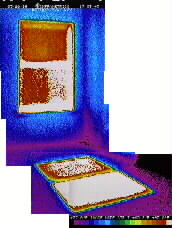
The improved glass has major implications for the required size for the air conditioning system. With 384 square feet of glass in our floor plan, Manual J showed a 7,700 Btu/hr difference (0.64 tons) in the required size of the air conditioning system - a large reason we are able to use an air conditioner half the size of that in the standard building. The windows provide excellent daylight transmittance as well as providing a color neutral appearance. Most visitors examining the PVRES home were unable to discern any visible difference in the appearance of the windows either from inside or out. However, the difference in the transmitted heat is clearly seen in the thermographic comparison shown in Figure 8.
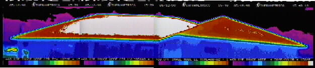
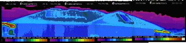
Reflective Roofing System Over the last five years, FSEC has conducted numerous residential experiments showing that white roofs can reduce cooling energy needs [6]. The average cooling energy reduction based on tests in a dozen homes converted to white roofs was 19%. Based on testing performed at the FSEC's Flexible Roof Facility in the summer of 1997, we learned that of the evaluated roofing systems (radiant barriers, added ventilation, white tile and white metal roofs), white tile provides the best cooling related performance of tested options [9]. Relative to a black asphalt shingle roof, a white tile roof produced a 76% reduction in overall summer ceiling heat flux (all test cells have R-19 ceiling insulation present). Moreover, when the outside summer air temperatures were at their peak the coincident peak attic air temperature difference which was 40oF lower in the white tile test cell (91.4oF) than the construction with black asphalt shingles (131.5oF). The measured attic air temperature is actually lower in the attic than the ambient air temperature until 2 PM in the afternoon on a typical summer day!(1) Both our test homes have R-30 fiberglass insulation blown in the attic, but two major differences for the PVRES home. The improved house features a white Mission concrete "S" tile roof - donated to the project by the Monier Company - to take advantage of its superior thermal performance. The control home's roof is conventional: popular gray-brown asphalt shingles. We had both roof materials evaluated by DSET Laboratories; the solar reflectance of the Monier white S-tile tested at 77% while the reflectance of the gray-brown architectural asphalt shingle was only 7%. The tile roof was installed on the PVRES home in January of 1998. As expected, infrared thermography of the roofs (Figure 9) revealed major differences in the thermal performance of the two roofs. Figure 10 shows a plot of the measured attic air and ambient temperatures in the two homes on the utility peak day of June 18th. The attic temperature in the control house rises quickly in the afternoon to reach a maximum of 137.9oF at 2:30 PM while the white tile roof attic only reaches 100.2oF - just about the same as the ambient air temperature.
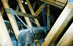
Low Friction Interior Duct System An innovative design feature in the PV home is its low-friction interior mounted duct system. In conventional houses (including our standard home) the ducts are frequently undersized and are almost always located in the hot attic (Figure 11). Previous research has shown that air handlers located in the attic space can increase space cooling by up to 30% [10]. Tests at FSEC has shown that not only does the attic sometimes reach 135oF in Florida's summers [14], heat transfer to the duct system can rob the air conditioner of up to a third of its cooling capacity during the hottest hours. The reason is simple: R-6 flex ducts contains the coldest air in the home (~60oF) while being exposed to the hottest temperatures; the area of ducts in a typical home is a third of the floor area. Heat transfer is proportional to surface area, thermal resistance and temperature difference: Q = UA (delta)T. At 130oF, and a 2,400 square foot home, this equates to over half a ton of air conditioning lost before cooling air reaches the registers.
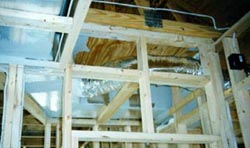
To avoid this problem, and to allow down-sizing of the PVRES air conditioning system, we designed the duct system so that it fits inside the conditioned space. Whatever heat is gained by the duct system is heat to be removed from the conditioned space. To hide the ducts, false dropped ceilings, lower cathedral sections and chases were used throughout the interior (Figure 12). To avoid problems with leakage, the duct system was carefully sealed with mastic and tested.
Finally, we oversized the duct system, so that air flow
resistance would be minimized. This not only provides critically
important air flow across the evaporator, it also reduces
air handler fan power and improves system efficiency while
lowering noise. Such high air flow, low friction duct systems
have shown to provide up to a 12% improvement in cooling
system efficiency at essentially no cost [15]. Duct slide
rules dominate the air conditioning industry with 0.1 inches
water column (IWC)/100 ft equivalent length almost universally
used to size ducts. Based on previous work, we found that
using a friction coefficient of 0.05 IWC/100 ft will achieve
the proper system air flow. A balometer mounted on the
AH return air grill was used to verify that the target
air flow was achieved (700 cfm/ton at full fan speed). 1. After World War II prior to wide spread air conditioning, white tile roofs were nearly universal in new construction in South Florida because of their perceived advantage promoting a cool home interior [20]. |
|||||||||||||||||||||||||||||||||||||||||||||||||||||||||||||||||||||||||||||||||||||||||||||||||||||||||||

© 2007-2014 University of Central Florida. The Florida Solar Energy Center (FSEC)
is a research institute of the
University of Central Florida.
For more information about FSEC, please contact us or learn more about us.
Find us on Facebook!